Mazda Protege 5. Manual - part 55
ON-BOARD DIAGNOSTIC [ENGINE CONTROL SYSTEM (FS)]
01–02B–40
End Of Sie
DTC P0117 [FS]
A3U010201084W14
Diagnostic procedure
DTC P0117
ECT circuit low input
DETECTION
CONDITION
•
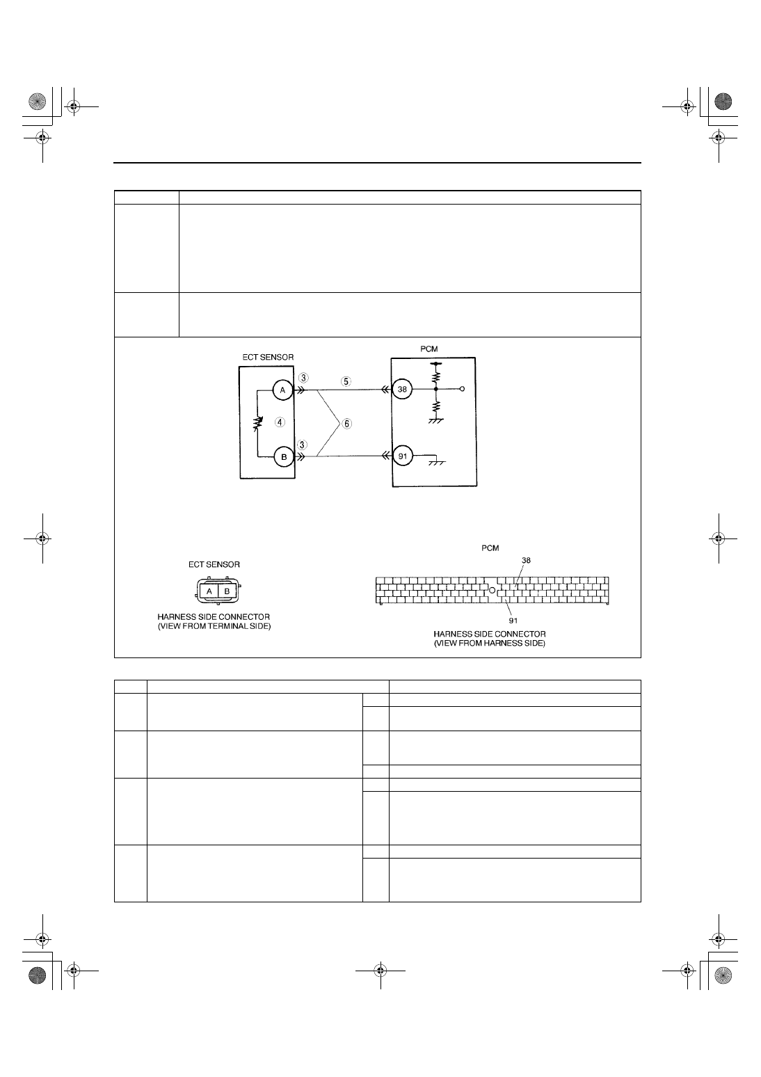
PCM monitors ECT sensor signal at PCM terminal 38. If voltage at terminal 38 is below 0.20 V, PCM
determines that ECT sensor circuit has malfunction.
Diagnostic support note
•
This is a continuous monitor (CCM).
•
MIL illuminates if PCM detects the above malfunction condition during first drive cycle. Therefore,
PENDING CODE is not available.
•
FREEZE FRAME DATA is available.
•
DTC is stored in PCM memory.
POSSIBLE
CAUSE
•
ECT sensor malfunction
•
Short to ground circuit between ECT sensor terminal A and PCM connector terminal 38
•
ECT signal and ground circuits are shorted each other.
•
PCM malfunction
STEP
INSPECTION
ACTION
1
VERIFY FREEZE FRAME DATA HAS BEEN
RECORDED
•
Has FREEZE FRAME DATA been recorded?
Yes Go to next step.
No
Record FREEZE FRAME DATA on repair order, then go to
next step.
2
VERIFY RELATED REPAIR INFORMATION
AVAILABILITY
•
Check for related Service Bulletins availability.
•
Is any related repair information available?
Yes Perform repair or diagnosis according to available repair
information.
•
If vehicle is not repaired, go to next step.
No
Go to next step.
3
INSPECT ECT SENSOR TERMINAL BENT
•
Turn ignition key to OFF.
•
Disconnect ECT sensor connector.
•
Check for bent of ECT sensor terminals A and
B (part-side).
•
Is there malfunction?
Yes Repair or replace terminal, then go to Step 7.
No
Go to next step.
4
CLASSIFY ECT SENSOR MALFUNCTION OR
HARNESS MALFUNCTION
•
Measure resistance between ECT sensor
teminals A and B (part-side).
•
Is resistance within 0.111—25.403 kilohms?
Yes Go to next step.
No
Replace ECT sensor, then go to Step 7.
1712-1U-01G(01-02B).fm 40 ページ 2001年6月29日 金曜日 午後3時24分