Mazda 5. Manual - part 54


  Index      Mazda     Mazda 5 - service repair manual


Search            


Content   ..  52  53  54  55   ..


Mazda 5. Manual - part 54


00–00–2

GENERAL INFORMATION 

General (L.H.D. R.H.D.) specs.

End Of Sie

VEHICLE IDENTIFICATION NUMBER (VIN)

DPE000000000B09

European (L.H.D.) specs.
JMZ CR1982*# 100001—
JMZ CR19F2*# 100001—
JMZ CR19F5*# 100001—
JMZ CR19R6*# 100001—
JMZ CR19T6*# 100001—

U.K. specs.
JMZ CR19820# 100001—
JMZ CR19F20# 100001—
JMZ CR19R60# 100001—
JMZ CR19T60# 100001—

General (L.H.D.) specs.
JM7 CR10F1*0 100001—
JM7 CR10F100 100001—

General (R.H.D.) specs.
JM6 CR10F100 100001—

End Of Sie

HOW TO USE THIS MANUAL

DPE000000000B01

Efficient Replacement of Body Panels

• This section contains information on the body panels in regard to the welding types, number of spot welds, and 

cut-and-join locations that are necessary for panel removal and installation.

• The type of weld and position are indicated by symbols.

• Some sections have notes concerning the operation being performed. Thoroughly read and understand the 

notes before carrying out any procedures.

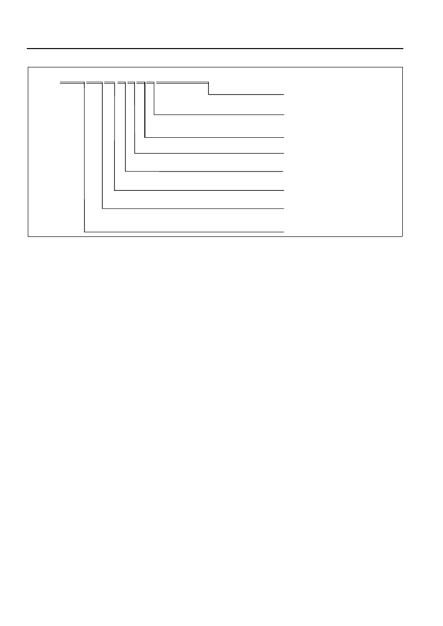
J  M 6 C R 10  F  1  0  0  1  2  3  4  5  6

Serial No.

Body style

F= LF (2.0 L)

CR= Mazda5

World manufacturer identification

0 = Dummy

1

10 = Closed body

JM6 = General (R.H.D.) specs.
JM7 = General (L.H.D.) specs.

No significance

5= 2005, 6= 2006
0 = Dummy

Model year

No significance

Engine type

Model change code

Vehicle type

DPE000ZW1006

GENERAL INFORMATION 

00–00–3

00

Example

Symbols of Panel Replacement

• The following 6 symbols are used to indicate the type of weld that is used when replacing body panels.

Body Dimensions (Flat-plane Dimensions)

• Flat-plane dimensions are the dimensions measured by projecting certain reference points onto a plane 

REAR FENDER PANEL REMOVAL

Shows operation section

Shows procedure, caution and note

BRAZE WELDING

Shows welding region

Shows a cross

Shows a insulator

Avoid cutting with a flame as the insulator (shaded) is flammable.

1.The rear fender panel and wheel house are joined with glue at the wheel arch line.

Drill the 17 weld locations indicated by (A), from the room side.

Caution

NOTE

CUT-AND-JOINT LOCATION

ROUGH CUT LOCATION

Shows a dimensions

{9.84in}

250mm

A-A

30mm

{1.18in}

Shows number of weld

Shows a cross location

A

A

(A)17

17

4

5

7

1

5

DPE2010B001

SYMBOL

MEANING

Spot welding

CO

2


arc welding (plug welding)

CO

2


spot welding

SYMBOL

MEANING

Continuous MIG welding (Cut-and-join location)

Braze welding 

Rough cut location

MZZ2010B002

00–00–4

GENERAL INFORMATION 

surface.

• When there are no specific indications, the standard points and dimensions are symmetrical in regard to the 

center of the vehicle.

• The hypothetical lines may differ according to the vehicle model.

• The schematic diagram shows the vehicle as it is projected from the underbody.

810 {31.89}

FLAT-PLANE DIMENSIONS

FRONT FENDER INSTALLATION NUT

DPE2010B010

GENERAL INFORMATION 

00–00–5

00

Example

Shows vehicle section

When  there are no specific indications, all of 
units are in millimeters (mm).

Shows outline drawing

Shows dimension

The dimensions on the left 
and right in regard to the center 
of the vehicle are different.

Shows hypothetical 
standard line

Shows point 
symbol

Point

symbol

Designation

Hole diameter

or bolt or nut 

size mm {in}

Crossmember No,1 standard 
hole

Front side frame standard hole
Front suspension mounting
block surface hole center

Front suspension mounting 
bolt 
Front frame rear standard hole

Front frame rear standard hole
Rear side frame standard hole

Link bracket

Rear suspension housing

A

B

C

D

E

F
G

H

I

J
K

Rear side frame standard hole

Rear side frame standard hole

Shows bolt size

Shows hole diameter

Shows 
slot

mm {in}

UNDERBODY FLAT-PLANE DIMENSIONS

φ 16 {0.62}

φ 16 {0.62}

φ 16 {0.62}

M14 {0.55}

φ 80 {3.14}

Point

symbol

Designation

Hole diameter

or bolt or nut 

size mm {in}

φ 16 {0.62}
φ 31 {1.22}

φ 12 {0.47}

Rear suspension housing

L

φ 12 {0.47}

φ 16 {0.62}

φ 18 {0.62}

17 

× 29.5

{0.66

×1.16}

A

B

C

D

E

F

G

H

I

J

K

L

1,016

{40.00}

687

{27.05}

420

182

93

144

120

{7.17} {3.66} {5.67} {4.72}

1,030

140

760

68

{5.51}

{2.68}

379

{16.54}

{40.55}

{29.92}

{14.92}

{25.75}

654

1,084

{42.84}

579

{22.80}

479

{18.86}

436

436

{17.17}

{17.17}

445

512

660

1,043

666

{17.52}

{20.16}

{25.98}

{41.06}

{26.22}

1,106

{43.54}

1,164

543

485

484

{21.37}

{19.05}

478

1,073

{37.91}

455

{17.91}

469

{18.46}

760

605

650

650

{29.92}

{23.82}

{25.59}

{25.59}

650

{45.83}

{25.59}

LH

RH

DPE2010B003


Content   ..  52  53  54  55   ..