Lexus SC300 / Lexus SC400. Manual - part 837
OK
NG
OK
NG
4
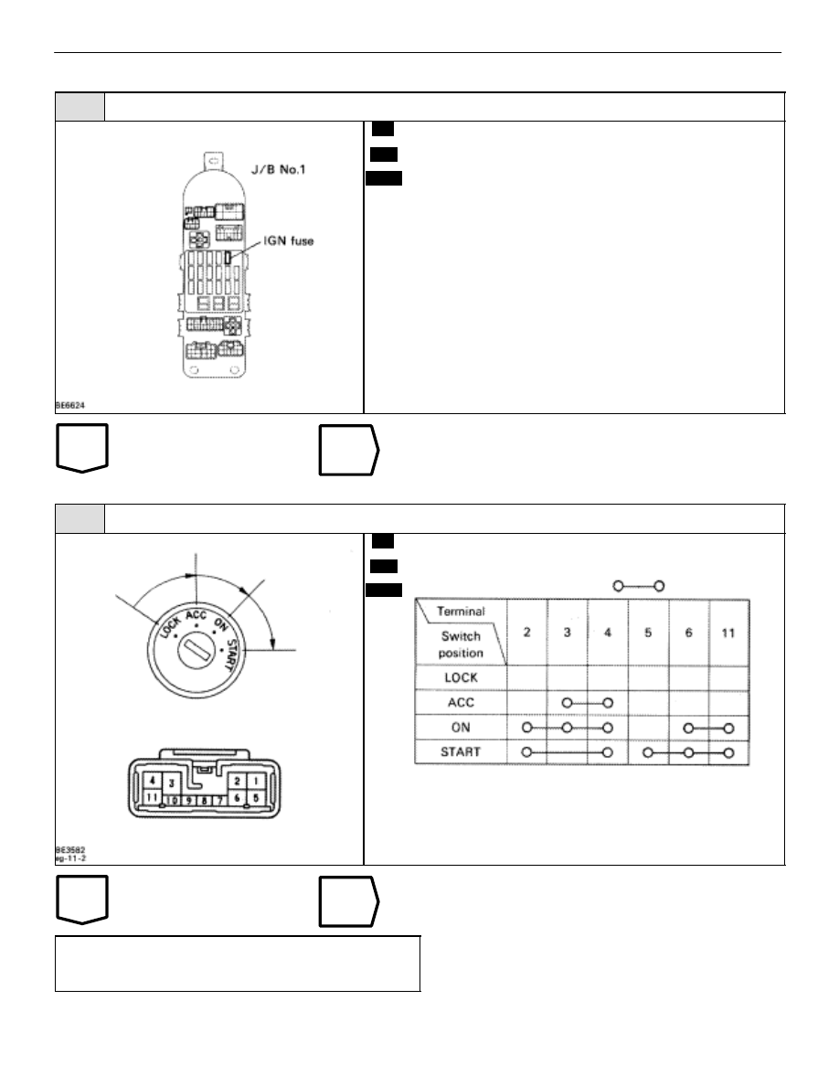
Check IGN Fuse.
C
OK
P
Remove IGN fuse from J/B No.1.
Check continuity of IGN fuse.
Continuity.
Check for short in all the harness and components con-
nected to IGN fuse (See attached wiring diagram).
5
Check ignition switch.
C
OK
P
Remove under cover and finish panel.
Check continuity between terminals.
continuity
Replace ignition switch.
Check and repair harness and connector between
battery and ignition switch, ignition switch and en-
gine & ECT ECU.
–
ENGINE TROUBLESHOOTING
Circuit Inspection
TR–127