Lexus SC300 / Lexus SC400. Manual - part 838
OK
NG
OK
NG
YES
NO
INSPECTION PROCEDURE
1
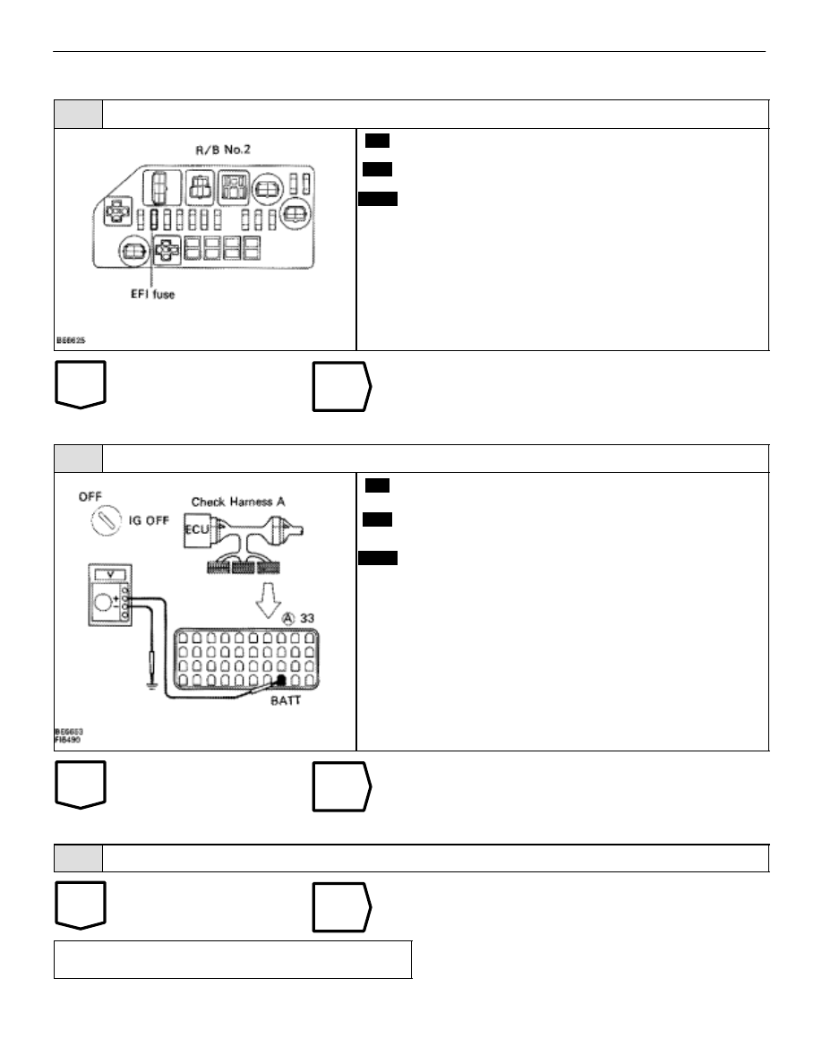
Check EFI fuse.
C
OK
P
Remove EFI fuse from R/B No. 2
Check continuity of EFI fuse.
Continuity
Check for short in all the harness and components
connected to EFI fuse (See attached wiring diagram).
2
Check voltage between terminal BATT of engine (& ECT) ECU connector and body ground.
C
OK
P
Connect the Check Harness A. (See page
Measure voltage between terminal BATT of engine
(& ECT) ECU connector and body ground.
Voltage: 10 – 14 V
Check and repair harness or connector between engine
(& ECT) ECU and EFI fuse, EFI fuse and battery.
3
Are the diagnostic trouble codes still in the memory when the ignition switch is turned OFF?
Check and replace engine (& ECT) ECU.
Proceed to next circuit inspection shown on
matrix chart (See page
).
–
ENGINE TROUBLESHOOTING
Circuit Inspection
TR–127