Jeep XJ. Manual - part 395


  Index      Jeep     Jeep XJ - service repair manual 2001 year


Search            


Content   ..  393  394  395  396   ..


Jeep XJ. Manual - part 395


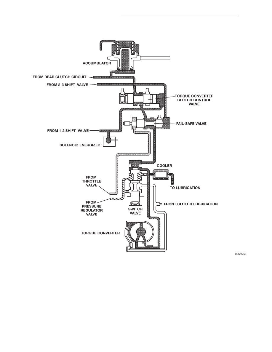
Fig. 34 Switch Valve-Torque Converter Locked

21 - 116

AUTOMATIC TRANSMISSION—30RH

XJ

DESCRIPTION AND OPERATION (Continued)

MANUAL VALVE

The manual valve (Fig. 35) is a relay valve. The

purpose of the manual valve is to direct fluid to the
correct circuit needed for a specific gear or driving
range. The manual valve, as the name implies, is
manually operated by the driver with a lever located
on the side of the valve body. The valve is connected
mechanically by either a cable or linkage to the gear-
shift mechanism. The valve is held in each of its
positions by a spring–loaded roller or ball that
engages the “roostercomb” of the manual valve.

ACCUMULATOR

DESCRIPTION

The accumulator (Fig. 36) is a hydraulic device

that has the sole purpose of cushioning the applica-
tion of a band or clutch. The accumulator consists of
a dual–land piston and a spring located in a bore in
the transmission case.

OPERATION

Line pressure is directed between the lands of the

piston (Fig. 37), bottoming it against the accumulator
plate. The accumulator stays in this position after
the transmission is placed into a Drive position.
When the 1–2 upshift occurs (Fig. 38), line pressure

is directed to the large end of the piston and then to
the kickdown servo. As the line pressure reaches the
accumulator, the combination of spring pressure and
line pressure forces the piston away from the accu-
mulator plate. This causes a balanced pressure situ-
ation, which results in a cushioned band application.
After the kickdown servo has become immovable, line
pressure will finish pushing the accumulator up into
its bore. When the large end of the accumulator pis-
ton is seated in its bore, the band or clutch is fully
applied.

Fig. 35 Manual Valve

1 – 1-2 GOVERNOR PLUG
2 – 2-3 GOVERNOR PLUG
3 – GOVERNOR REAR CLUTCH ACCUMULATOR
4 – THROTTLE VALVE

5 – LAND #1
6 – PUMP
7 – PRESSURE REGULATOR
8 – LAND #2

Fig. 36 Accumulator

1 – ACCUMULATOR PISTON
2 – PISTON SPRING

XJ

AUTOMATIC TRANSMISSION—30RH

21 - 117

DESCRIPTION AND OPERATION (Continued)

NOTE: The accumulator is shown in the inverted
position for illustrative purposes.

PISTONS

DESCRIPTION

There are several sizes and types of pistons used in

an automatic transmission. Some pistons are used to
apply clutches, while others are used to apply bands.
They all have in common the fact that they are round or
circular in shape, located within a smooth walled cylin-
der, which is closed at one end and converts fluid pres-
sure into mechanical movement. The fluid pressure
exerted on the piston is contained within the system
through the use of piston rings or seals.

OPERATION

The principal which makes this operation possible is

known as Pascal’s Law. Pascal’s Law can be stated as:
“Pressure on a confined fluid is transmitted equally in
all directions and acts with equal force on equal areas.”

PRESSURE

Pressure (Fig. 39) is nothing more than force (lbs.)

divided by area (in or ft.), or force per unit area.
Given a 100 lb. block and an area of 100 sq. in. on
the floor, the pressure exerted by the block is: 100
lbs. 100 in or 1 pound per square inch, or PSI as it is
commonly referred to.

PRESSURE ON A CONFINED FLUID

Pressure is exerted on a confined fluid (Fig. 40) by

applying a force to some given area in contact with the
fluid. A good example of this is a cylinder filled with
fluid and equipped with a piston that is closely fitted to
the cylinder wall. If a force is applied to the piston,
pressure will be developed in the fluid. Of course, no

Fig. 37 Accumulator in Neutral and Drive Positions

Fig. 38 Accumulator in Second Gear Position

1 – BOTTOM IN BORE
2 – SHUTTLE VALVE

Fig. 39 Force and Pressure Relationship

21 - 118

AUTOMATIC TRANSMISSION—30RH

XJ

DESCRIPTION AND OPERATION (Continued)

pressure will be created if the fluid is not confined. It
will simply “leak” past the piston. There must be a
resistance to flow in order to create pressure. Piston
sealing is extremely important in hydraulic operation.
Several kinds of seals are used to accomplish this
within a transmission. These include but are not limited
to

O–rings,

D–rings,

lip

seals,

sealing

rings,

or

extremely close tolerances between the piston and the
cylinder wall. The force exerted is downward (gravity),
however, the principle remains the same no matter
which direction is taken. The pressure created in the
fluid is equal to the force applied, divided by the piston
area. If the force is 100 lbs., and the piston area is 10
sq. in., then the pressure created equals 10 PSI.
Another interpretation of Pascal’s Law is that regard-
less of container shape or size, the pressure will be
maintained throughout, as long as the fluid is confined.
In other words, the pressure in the fluid is the same
everywhere within the container.

FORCE MULTIPLICATION

Using the 10 PSI example used in the illustration

(Fig. 41), a force of 1000 lbs. can be moved with a
force of only 100 lbs. The secret of force multiplica-
tion in hydraulic systems is the total fluid contact
area employed. The illustration, (Fig. 41), shows an
area that is ten times larger than the original area.
The pressure created with the smaller 100 lb. input
is 10 PSI. The concept “pressure is the same every-
where” means that the pressure underneath the
larger piston is also 10 PSI. Pressure is equal to the
force applied divided by the contact area. Therefore,
by means of simple algebra, the output force may be
found. This concept is extremely important, as it is
also used in the design and operation of all shift
valves and limiting valves in the valve body, as well
as the pistons, of the transmission, which activate
the clutches and bands. It is nothing more than

using a difference of area to create a difference in
pressure to move an object.

PISTON TRAVEL

The relationship between hydraulic lever and a

mechanical lever is the same. With a mechanical
lever it’s a weight–to–distance output rather than a
pressure–to–area output. Using the same forces and
areas as in the previous example, the smaller piston
(Fig. 42) has to move ten times the distance required
to move the larger piston one inch. Therefore, for
every inch the larger piston moves, the smaller pis-
ton moves ten inches. This principle is true in other
instances also. A common garage floor jack is a good
example. To raise a car weighing 2000 lbs., an effort
of only 100 lbs. may be required. For every inch the
car moves upward, the input piston at the jack han-
dle must move 20 inches downward.

Fig. 40 Pressure on a Confined Fluid

Fig. 41 Force Multiplication

Fig. 42 Piston Travel

XJ

AUTOMATIC TRANSMISSION—30RH

21 - 119

DESCRIPTION AND OPERATION (Continued)


Content   ..  393  394  395  396   ..