Jeep XJ. Manual - part 378


  Index      Jeep     Jeep XJ - service repair manual 2001 year


Search            


Content   ..  376  377  378  379   ..


Jeep XJ. Manual - part 378


(3) Carefully guide propeller shaft slip yoke into

housing and onto output shaft splines.

(4) Align marks made at removal and connect pro-

peller shaft to rear axle pinion yoke.

REAR HOUSING YOKE BUSHING

REMOVAL

(1) Remove housing yoke seal.
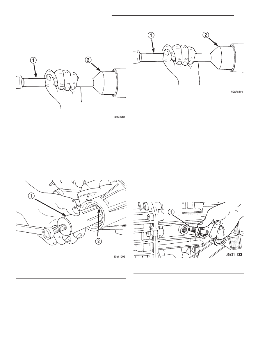
(2) Insert Remover 6957 into rear housing. Tighten

tool to bushing and remove bushing (Fig. 12).

INSTALLATION

(1) Align bushing oil hole with oil slot in rear

housing.

(2) Tap bushing into place with Installer 6951 and

Handle C-4171.

(3) Install new oil seal in housing using Seal

Installer C-3972–A (Fig. 13).

DISASSEMBLY AND ASSEMBLY

TRANSMISSION

DISASSEMBLY

FRONT HOUSING

(1) If necessary, temporarily reinstall shift lever

assembly. Shift transmission into Neutral.

(2) If lubricant was not drained out of transmis-

sion during removal, remove drain plug and drain
lubricant into container at this time.

(3) Inspect drain plug magnet for debris.
(4) Remove backup light switch. Switch is located

on passenger side of rear housing (Fig. 14).

(5) If necessary, remove shift tower bolts and

remove tower and lever assembly (Fig. 15).

(6) Remove shift shaft lock bolt (Fig. 16). Bolt is

located at top of front housing just forward of shift
tower. Bolt is a shoulder bolt that secures the shift
shaft bushing and lever.

(7) Use Remover 8117 and suitable slide hammer

to remove shift shaft detent plug.

Fig. 11 Installing Transmission Housing Yoke Seal

1 – SPECIAL TOOL C-4171
2 – SPECIAL TOOL C-3972–A

Fig. 12 Bushing Removal—Typical

1 – REMOVER 6957
2 – EXTENSION HOUSING BUSHING

Fig. 13 Rear Housing Seal Installation

1 – SPECIAL TOOL C-4171
2 – SPECIAL TOOL C-3972–A

Fig. 14 Backup Light Switch Location

1 – BACKUP LIGHT SWITCH

21 - 48

NV3550 MANUAL TRANSMISSION

XJ

REMOVAL AND INSTALLATION (Continued)

(8) Remove shift shaft detent plunger and spring

(Fig. 17). Use pencil magnet to remove spring then
plunger, if necessary.

(9) Remove bolts attaching input shaft bearing

retainer to front housing (Fig. 18).

Fig. 15 Shift Tower Removal

1 – SHIFT TOWER AND LEVER ASSEMBLY
2 – SHIFT SOCKET
3 – SEAL

Fig. 16 Shift Shaft Lock Bolt Removal

1 – SHIFT SHAFT LOCK BOLT
2 – SHAFT SOCKET

Fig. 17 Detent Plunger And Spring Removal

1 – FRONT HOUSING
2 – PLUG
3 – SPRING
4 – PLUNGER

Fig. 18 Input Shaft Bearing Retainer Bolt Removal—

Typical

1 – INPUT SHAFT BEARING RETAINER
2 – RETAINER BOLTS

XJ

NV3550 MANUAL TRANSMISSION

21 - 49

DISASSEMBLY AND ASSEMBLY (Continued)

(10) Remove input shaft bearing retainer. Use pry

tool to carefully lift retainer and break sealer bead
(Fig. 19).

(11) Remove bearing retainer from input shaft

(Fig. 20).

(12) Remove snap ring that secures input shaft in

front bearing (Fig. 21).

(13) Remove bolts that attach front housing to rear

housing (Fig. 22). Three bolts at extreme rear of
housing are actually for the output shaft bearing
retainer. It is not necessary to remove all three bolts
at this time. Leave at least one bolt in place until
geartrain is ready to be removed from case.

Fig. 19 Loosening Bearing Retainer Sealer

Bead—Typical

1 – PRY TOOL
2 – INPUT SHAFT BEARING RETAINER

Fig. 20 Input Shaft Bearing Retainer Removal—

Typical

1 – SHAFT BEARING
2 – BEARING RETAINER
3 – INPUT SHAFT

Fig. 21 Input Shaft Snap Ring Removal—Typical

1 – INPUT SHAFT SNAP RING
2 – OIL FEED

Fig. 22 Housing And Bearing Retainer Bolt

Locations

1 – RETAINER BOLTS
2 – HOUSING BOLTS
3 – RETAINER BOLT
4 – HOUSING BOLT LOCATIONS

21 - 50

NV3550 MANUAL TRANSMISSION

XJ

DISASSEMBLY AND ASSEMBLY (Continued)

(14) Separate front housing from rear housing

(Fig. 23). Use plastic mallet to tap front housing off
alignment dowels.

(15) Remove and inspect input shaft bearing.

Inspect countershaft front bearing race (Fig. 24).

(16) Note position of input shaft, shift shaft and

forks, and geartrain components in housing (Fig. 25).

SHIFT SHAFT, SHIFT FORKS AND REVERSE IDLER SEGMENT

(1) Unseat the roll pin that secures the shift

socket tot he shift shaft with Special Tool 6858 as fol-
lows:

(a) Position Tool 6858 on the shift shaft. Center

the tool over the roll pin and verify that the tool
legs are firmly seated on the shift socket (Fig. 26).

(b) Tilt the socket toward the side of the case.

This positions the roll pin at a slight angle to avoid
trapping the pin between the gear teeth.

(c) Tighten the tool punch to press the roll pin

downward and out of the shift socket (Fig. 26). The
roll pin does not have to be completely removed
from the shift socket. The roll pin must only be
clear of the shift shaft. Be careful not to push the
pin into the geartrain.
(2) Using a hammer and suitable punch, drive out

roll pin that secures shift bushing and lever to shift
shaft (Fig. 27).

NOTE: Be sure to use the proper size punch to
avoid bending the shift shaft.

Fig. 23 Front Housing Removal

1 – FRONT HOUSING
2 – REAR HOUSING
3 – DOWELS (2)
4 – PLASTIC MALLET

Fig. 24 Input Shaft Bearing and Countershaft Front

Bearing Race Location

1 – INPUT SHAFT BEARING
2 – FRONT HOUSING
3 – COUNTERSHAFT FRONT BEARING

Fig. 25 Geartrain And Shift Component

Identification

1 – SHIFT SHAFT
2 – BUSHING
3 – REAR HOUSING
4 – REVERSE IDLER AND SUPPORT
5 – OUTPUT SHAFT AND GEARS
6 – COUNTERSHAFT
7 – 1–2 FORK
8 – INPUT SHAFT
9 – 3–4 FORK

XJ

NV3550 MANUAL TRANSMISSION

21 - 51

DISASSEMBLY AND ASSEMBLY (Continued)


Content   ..  376  377  378  379   ..