Jeep Wrangler TJ. Manual - part 534


  Index      Jeep     Jeep Wrangler TJ - service repair manual 2005 year


Search            


Content   ..  532  533  534  535   ..


Jeep Wrangler TJ. Manual - part 534


(7) Install new seal in rear extension housing with

Installer 9041 and Handle C-4171.

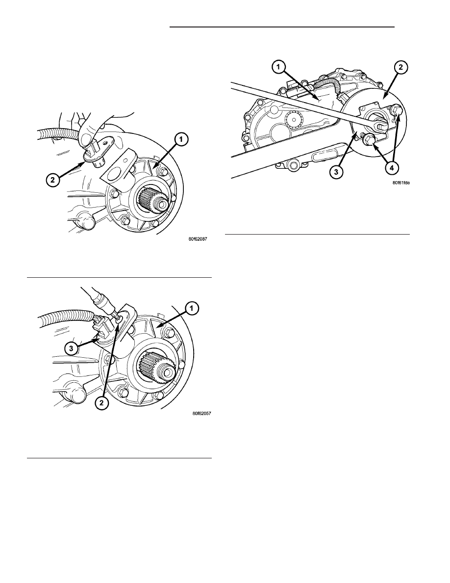
(8) Install the speedometer sensor (Fig. 89) into

the extension housing.

(9) Install the speedometer sensor bolt (Fig. 90).

Tighten the bolt to 11-16 N·m (8-12 ft.lbs.).

(10) Install the rear companion flange onto the

output shaft.

(11) Install bolts into two threaded holes in the

rear propeller shaft companion flange 180° apart
(Fig. 91).

(12) Place the Holder 6719 (Fig. 91) over the two

bolts and use the Holder to install a new rear com-
panion flange nut. Never re-use the companion
flange nut once it has been installed. Tighten the
companion flange nut to 122-176 N·m (90-130 ft.lbs.).

INSTALLATION

(1) Align and seat transfer case on transmission.

Be sure transfer case input gear splines are aligned
with transmission output shaft. Align splines by
rotating transfer case rear output shaft yoke if nec-
essary. Do not install any transfer case attaching
nuts until the transfer case is completely seated
against the transmission.

(2) Install and tighten transfer case attaching

nuts. Tighten nuts to 30-41 N·m (20-30 ft.lbs.).

(3) Install rear crossmember.
(4) Remove jack stand from under transmission.
(5) Align and connect propeller shafts. (Refer to 3 -

DIFFERENTIAL

&

DRIVELINE/PROPELLER

SHAFT/PROPELLER SHAFT - INSTALLATION)

(6) Connect vacuum harness and vent hose.
(7) Connect shift rod to transfer case lever or floor

shift arm. Use channel lock style pliers to press rod
back into lever grommet.

(8) Adjust shift linkage, if necessary.
(9) Fill transfer case with recommended transmis-

sion fluid and install fill plug.

(10) Install skid plate, if equipped. (Refer to 13 -

FRAMES & BUMPERS/FRAME/TRANSFER CASE
SKID PLATE - INSTALLATION)

(11) Lower vehicle

Fig. 89 Speedometer Sensor Installation

1 - EXTENSION HOUSING
2 - SPEEDOMETER SENSOR

Fig. 90 Speedometer Sensor Bolt Installation

1 - EXTENSION HOUSING
2 - BOLT
3 - SPEEDOMETER SENSOR

Fig. 91 Rear Companion Flange Nut Removal

1 - TRANSFER CASE
2 - HOLDER 6719
3 - COMPANION FLANGE
4 - BOLTS

21 - 226

TRANSFER CASE - NV241

TJ

TRANSFER CASE - NV241 (Continued)

SPECIFICATIONS

TRANSFER CASE - NV241

TORQUE SPECIFICATIONS

DESCRIPTION

N·m

Ft. Lbs.

In. Lbs.

Plug, Detent

16-25

12-18

-

Plug, Drain/Fill

20-34

15-25

-

Bolt, Rear Extension

16-24

12-18

-

Bolt, Front Input Retainer

21

16

-

Bolt, Case Half

20-27

15-20

-

Nut, Front Yoke

122-176

90-130

-

Nut, Rear Companion Flange

258-312

190-230

-

Bolt, Shift Lever

20-34

15-25

-

Nuts, Mounting

30-41

20-30

-

Bolts, U-Joint

19

17

-

Support, Sector

27-42

20-30

-

Sensor, Transfer Case Position

20-34

16-25

-

Bolt, Speed Sensor

11-16

8-12

-

SPECIAL TOOLS

TRANSFER CASE - NV241

Puller - C-452

Handle, Universal - C-4171

Remover - L-4454

Installer, Bushing - 5066

Holder, Yoke - 6719A

TJ

TRANSFER CASE - NV241

21 - 227

TRANSFER CASE - NV241 (Continued)

Installer, Bearing - 6953

Spanner Wrench - 6958

Cup - 8148

Installer, Bearing - 8239

Remover - 8240

Installer, Seal - 8841

Flange Puller - 8992

Installer, Cup Seal - 9045

Installer, Bearing - 9047

21 - 228

TRANSFER CASE - NV241

TJ

REAR EXTENSION SEAL (Continued)

REAR EXTENSION SEAL

REMOVAL

(1) Raise and support vehicle.
(2) Remove rear propeller shaft. (Refer to 3 - DIF-

FERENTIAL & DRIVELINE/PROPELLER SHAFT/
PROPELLER SHAFT - REMOVAL)

(3) Remove the rear companion flange from the

output shaft.

(4) Using a suitable pry tool or slide-hammer

mounted screw, remove the rear extension seal.

INSTALLATION

(1) Clean fluid residue from sealing surface and

inspect for defects.

(2) Using

Installer

9041

and

Handle

C-4171,

install seal in rear extension (Fig. 92).

(3) Install the companion flange onto the output

shaft.

(4) Install a new companion flange nut and tighten

to 176-271 N·m (130-200 ft.lbs.).

(5) Install propeller shaft. (Refer to 3 - DIFFER-

ENTIAL & DRIVELINE/PROPELLER SHAFT/PRO-
PELLER SHAFT - INSTALLATION)

(6) Verify proper transfer case fluid level.
(7) Lower vehicle.

FLUID

STANDARD PROCEDURE - FLUID DRAIN AND
FILL

The fill and drain plugs are both in the rear case

(Fig. 93). Correct fill level is to the bottom edge of
the fill plug hole. Be sure the vehicle is level to
ensure an accurate fluid level check.

FRONT OUTPUT SHAFT SEAL

REMOVAL

(1) Shift transfer case into NEUTRAL.
(2) Raise vehicle.
(3) Remove front propeller shaft. (Refer to 3 - DIF-

FERENTIAL & DRIVELINE/PROPELLER SHAFT/
PROPELLER SHAFT - REMOVAL)

(4) Using Spanner Wrench 6958, remove yoke nut

(Fig. 94). Discard nut after removal. It is not reus-
able.

Fig. 92 Install Rear Extension Seal

1 - SPECIAL TOOL C-4171
2 - SPECIAL TOOL 9041

Fig. 93 Transfer Case Identification Tag and

Fill/Drain Plugs

1 - IDENTIFICATION TAG
2 - FILL PLUG
3 - DRAIN PLUG

Fig. 94 Front Yoke Nut Removal

1 - TRANSFER CASE
2 - HOLDER 6958
3 - FRONT YOKE

TJ

TRANSFER CASE - NV241

21 - 229


Content   ..  532  533  534  535   ..