Jeep Wrangler TJ. Manual - part 533


  Index      Jeep     Jeep Wrangler TJ - service repair manual 2005 year


Search            


Content   ..  531  532  533  534   ..


Jeep Wrangler TJ. Manual - part 533


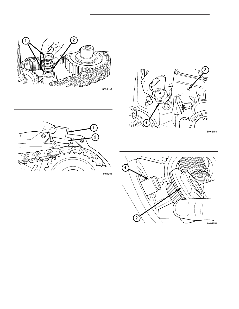
(8) Install spring and cups on shift rail (Fig. 73).

(9) Insert magnet in front case pocket (Fig. 74).

OIL PUMP AND REAR CASE

CAUTION: Do not remove the bolts holding the oil
pump cover to the rear case half. The oil pump
cover is aligned to the rear output shaft inner bear-
ing race and will become mis-aligned if the bolts
are loosened. If the transfer case failure has gener-
ated any debris which may have become trapped in
the oil pump. the rear case and oil pump assembly
MUST be replaced.

Lubricate the oil pump components before installa-

tion. Prime the oil pickup tube by pouring a little oil
into the tube before installation.

(1) Install new o-ring in pickup tube inlet of oil

pump.

(2) Position oil pickup tube and filter in rear case.

Be sure pickup filter is seated in case pocket and
that pickup tube is aligned in case notches. Be sure

hose that connects tube to filter is securely posi-
tioned.

(3) Install the transfer case position sensor (Fig.

75). Tighten the sensor to 20-34 N·m (16-25 ft.lbs.).

(4) Install the shift sector support (Fig. 76).

Tighten the sector support to 27-42 N·m (20-30
ft.lbs.).

Fig. 73 Shift Rail Spring And Cups Installation

1 - CUPS (2)
2 - SPRING

Fig. 74 Case Magnet Installation

1 - MAGNET
2 - CASE POCKET

Fig. 75 Install Transfer Case Position Sensor

1 - TRANSFER CASE POSITION SENSOR
2 - TRANSFER CASE

Fig. 76 Shift Sector Support Installation

1 - SHIFT SECTOR SHAFT
2 - SECTOR SUPPORT

21 - 222

TRANSFER CASE - NV241

TJ

TRANSFER CASE - NV241 (Continued)

(5) Install detent plunger and spring into the front

case half. (Fig. 77).

(6) Install new o-ring on detent plug and install

plug in front case (Fig. 77). Tighten plug to 16-25
N·m (12-18 ft. lbs.).

(7) Install shift lever onto the sector shaft (Fig.

78).

(8) Install the shift lever bolt (Fig. 79). Tighten the

bolt to 20-34 N·m (15-25 ft.lbs.)

(9) Shift the transfer case into a 4WD range. This

will raise the mainshaft slightly and make installa-
tion of the rear case half much easier.

(10) Verify that the transfer case alignment dowels

are properly installed.

(11) Apply bead of Mopar

t Gasket Maker, or

equivalent, to mating surface of front case. Keep
sealer bead width to maximum of 3/16 inch. Do not
use excessive amount of sealer as excess will be dis-
placed into case interior.

(12) Align oil pump with mainshaft and align shift

rail with bore in rear case. Then install rear case and
oil pump assembly (Fig. 80). Be sure oil pickup tube
remains in position during case installation.

(13) Install 4-5 rear case-to front case bolts to hold

rear case in position. Tighten bolts snug but not to
specified torque at this time.

Fig. 77 Detent Plug, Spring, and Plunger Installation

1 - DETENT PLUG
2 - SPRING
3 - PLUNGER

Fig. 78 Shift Lever Installation

1 - SHIFT LEVER
2 - SECTOR SUPPORT
3 - SHIFT SECTOR

Fig. 79 Shift Lever Bolt Installation

1 - SHIFT LEVER
2 - BOLT
3 - SECTOR SUPPORT

Fig. 80 Rear Case Half Installation

1 - REAR CASE HALF
2 - FRONT CASE HALF

TJ

TRANSFER CASE - NV241

21 - 223

TRANSFER CASE - NV241 (Continued)

CAUTION: Verify that shift rail, and case alignment
dowels (Fig. 81) are seated before installing any
bolts. Case could be cracked if shaft rail or dowels
are misaligned.

(14) Apply Loctite™ 242 to remainder of rear case-

to-front case bolt threads and install bolts (Fig. 82).
Tighten all bolts to 20-27 N·m (15-20 ft. lbs.).

YOKE

(1) Install yoke seal onto front shaft (Fig. 83).

(2) Install yoke onto front shaft (Fig. 84). Then

install and tighten a new yoke nut to 122-176 N·m
(90-130 ft. lbs.) torque. Never re-use a yoke nut.

Fig. 81 Case Alignment Dowel

1 - REAR CASE HALF
2 - FRONT CASE HALF
3 - ALIGNMENT DOWEL

Fig. 82 Case Half Bolt Installation

1 - REAR CASE HALF
2 - FRONT CASE HALF
3 - BOLTS

Fig. 83 Installing Flange Seal On Front Shaft

1 - FRONT OUTPUT SHAFT
2 - FLANGE SEAL

Fig. 84 Front Yoke Installation

1 - TRANSFER CASE
2 - FRONT YOKE

21 - 224

TRANSFER CASE - NV241

TJ

TRANSFER CASE - NV241 (Continued)

REAR EXTENSION

(1) Clean mating surfaces of transfer case housing

and the rear retainer of any original gasket material.

(2) Apply bead of Mopar

t Gasket Maker, or equiv-

alent, to mating surface of rear case. Keep sealer
bead width to maximum of 3/16 inch. Do not use
excessive amount of sealer as excess will be displaced
into case interior.

(3) Install the tone wheel dowel pin (Fig. 85) into

the output shaft.

(4) Install the speedometer sensor tone wheel (Fig.

86) onto the output shaft with the notch in the tone
wheel inner diameter toward the front of the transfer
case. Make sure the notch fits over the dowel pin in
the output shaft and the tone wheel is against the
rear output shaft bearing inner race.

(5) Align and install rear extension on rear case

(Fig. 87).

(6) Apply Mopar

t Silicone Sealer to threads of rear

extension bolts. Then install extension bolts (Fig. 88).
Tighten the extension bolts to 16-25 N·m (12-18
ft.lbs.).

Fig. 85 Output Shaft Dowel Pin

1 - TRANSFER CASE
2 - OUPUT SHAFT
3 - DOWEL PIN

Fig. 86 Speedometer Sensor Tone Wheel Installation

1 - TRANSFER CASE
2 - OUPUT SHAFT
3 - SENSOR TONE WHEEL

Fig. 87 Rear Extension Installation

1 - TRANSFER CASE
2 - EXTENSION HOUSING

Fig. 88 Rear Extension Bolt Installation

1 - EXTENSION HOUSING
2 - BOLTS

TJ

TRANSFER CASE - NV241

21 - 225

TRANSFER CASE - NV241 (Continued)


Content   ..  531  532  533  534   ..