Jeep Wrangler TJ. Manual - part 532


  Index      Jeep     Jeep Wrangler TJ - service repair manual 2005 year


Search            


Content   ..  530  531  532  533   ..


Jeep Wrangler TJ. Manual - part 532


(8) Install the input gear to the low range plane-

tary assembly and the input gear bearing.

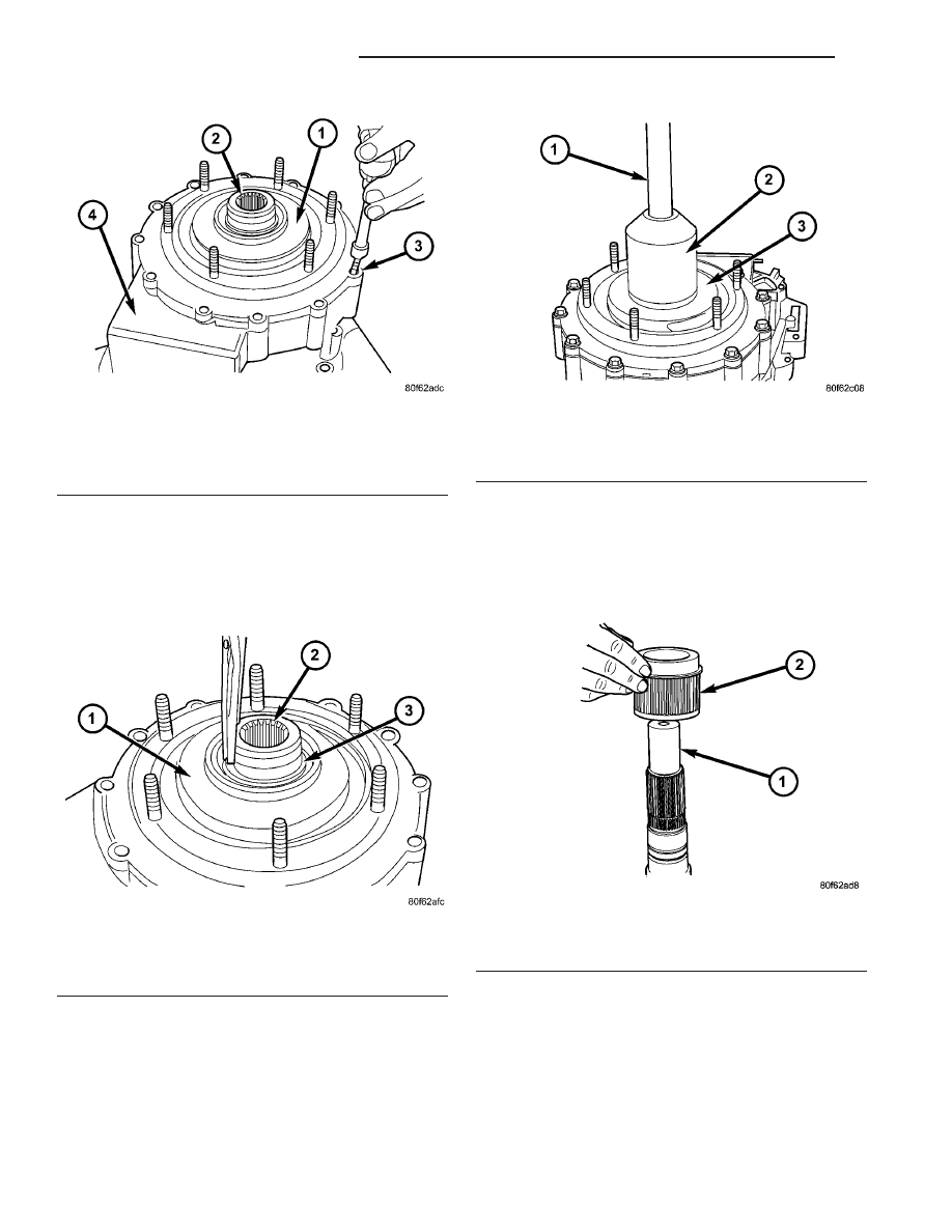
(9) Install the input gear retaining snap-ring (Fig.

57) onto the input gear.

(10) Install new oil seal in front input retainer

with Installer 8841 and Handle C-4171 (Fig. 58).

SHIFT FORKS AND MAINSHAFT

(1) Lubricate mainshaft splines with recommended

transmission fluid.

(2) Install the drive sprocket drive hub onto the

mainshaft (Fig. 59). Verify that the long shoulder is
towards the front of the mainshaft.

Fig. 56 Front Input Retainer Bolt Installation

1 - INPUT RETAINER
2 - INPUT GEAR
3 - BOLT
4 - FRONT CASE HALF

Fig. 57 Input Gear Snap-Ring Installation

1 - INPUT RETAINER
2 - INPUT GEAR
3 - SNAP-RING

Fig. 58 Input Gear Seal Installation

1 - HANDLE C-4171
2 - INSTALLER 8841
3 - INPUT RETAINER

Fig. 59 Drive Sprocket Drive Hub Installation

1 - MAINSHAFT
2 - DRIVE SPROCKET DRIVE HUB

21 - 218

TRANSFER CASE - NV241

TJ

TRANSFER CASE - NV241 (Continued)

(3) Install the mode hub (Fig. 60) onto the main-

shaft.

(4) Install the mode hub snap-ring (Fig. 61) onto

the mainshaft.

(5) Rotate the mainshaft 180° and install the slid-

ing clutch gear (Fig. 62) onto the drive sprocket drive
hub.

(6) Install the mainshaft drive sprocket (Fig. 63)

onto the drive hub.

(7) Install the mainshaft drive sprocket retaining

ring (Fig. 64) onto the drive hub.

Fig. 60 Mode Hub Installation

1 - MAINSHAFT
2 - MODE HUB

Fig. 61 Mode Hub Snap-Ring Installation

1 - MAINSHAFT
2 - MODE HUB
3 - SNAP-RING

Fig. 62 Sliding Clutch Gear Installation

1 - MAINSHAFT
2 - SLIDING CLUTCH GEAR

Fig. 63 Mainshaft Drive Sprocket Installation

1 - MAINSHAFT
2 - DRIVE SPROCKET

Fig. 64 Mainshaft Drive Sprocket Snap-Ring Installation

1 - MAINSHAFT
2 - DRIVE SPROCKET
3 - SNAP-RING

TJ

TRANSFER CASE - NV241

21 - 219

TRANSFER CASE - NV241 (Continued)

(8) Support front case on wood blocks so case inte-

rior is facing up. Place blocks between mounting
studs on forward surface of case.

(9) Lubricate mainshaft components with trans-

mission fluid.

(10) Lubricate sector shaft with transmission fluid

and install shift sector in case (Fig. 65). Position slot
in sector so it will be aligned with shift fork pin
when shift forks are installed.

(11) Assemble and install range fork and hub (Fig.

66). Be sure hub is properly seated in low range gear
and engaged to the input gear.

(12) Align and insert range fork pin in shift sector

slot.

(13) Install mode fork and mode sleeve (Fig. 67).

Verify that the long side of the mode sleeve is
towards the front of the transfer case.

(14) Install the shift rail (Fig. 68) through the shift

forks and into the shift rail pocket in the front case
half.

Fig. 65 Shift Sector Installation

1 - FRONT CASE HALF
2 - SHIFT SECTOR

Fig. 66 Range Fork and Hub Installation

1 - RANGE FORK
2 - RANGE HUB

Fig. 67 Mode Fork and Sleeve Installation

1 - MODE FORK
2 - MODE SLEEVE

Fig. 68 Shift Fork Rail Installation

1 - FRONT CASE HALF
2 - SHIFT RAIL

21 - 220

TRANSFER CASE - NV241

TJ

TRANSFER CASE - NV241 (Continued)

FRONT OUTPUT SHAFT AND DRIVE CHAIN

(1) Install front output shaft into the font output

shaft bearing (Fig. 69).

(2) Install the front output shaft snap-ring onto

the front output shaft.

(3) Install new front output seal (Fig. 70) in front

case with Installer 9041 and Handle C-4171.

(4) Insert front sprocket in drive chain (Fig. 71).
(5) Install drive chain around mainshaft drive

sprocket (Fig. 71). Then position front sprocket over
front output shaft.

(6) Install the mainshaft into the range hub and

mode sleeve and seat the front drive sprocket onto
the front output shaft (Fig. 71).

(7) Install the front drive sprocket retaining ring

(Fig. 72).

Fig. 69 Front Output Shaft Installation

1 - FRONT CASE HALF
2 - FRONT OUTPUT SHAFT

Fig. 70 Front Output Shaft Seal Installation

1 - HANDLE C-4171
2 - INSTALLER 9041

Fig. 71 Install Mainshaft, Drive Chain, and Front

Sprocket

1 - MAINSHAFT
2 - DRIVE CHAIN
3 - DRIVE SPROCKET

Fig. 72 Front Drive Sprocket Snap-Ring Installation

1 - DRIVE CHAIN
2 - FRONT DRIVE SPROCKET
3 - SNAP-RING

TJ

TRANSFER CASE - NV241

21 - 221

TRANSFER CASE - NV241 (Continued)


Content   ..  530  531  532  533   ..