Jeep Wrangler TJ. Manual - part 530


  Index      Jeep     Jeep Wrangler TJ - service repair manual 2005 year


Search            


Content   ..  528  529  530  531   ..


Jeep Wrangler TJ. Manual - part 530


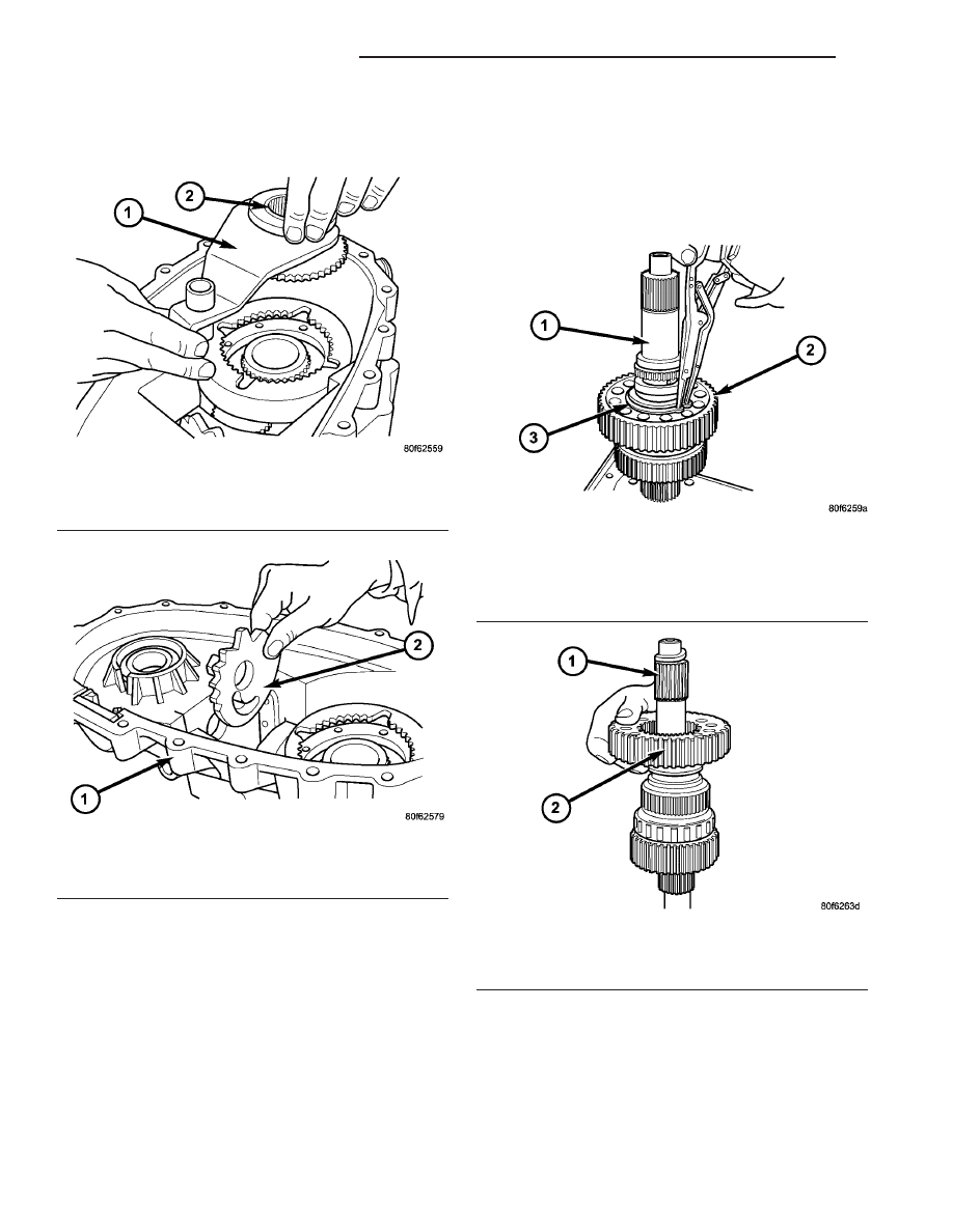
(4) Remove range fork and hub as an assembly

(Fig. 27). Note fork position for installation reference.

(5) Remove shift sector (Fig. 28).

MAINSHAFT

(1) Remove the snap-ring that secures the chain

drive sprocket onto mainshaft (Fig. 29). Use standard
(instead of parallel jaw) snap-ring pliers to remove
this snap-ring.

(2) Remove drive sprocket (Fig. 30).

Fig. 27 Range Fork and Hub Removal

1 - RANGE FORK
2 - RANGE HUB

Fig. 28 Shift Sector Removal

1 - FRONT CASE HALF
2 - SHIFT SECTOR

Fig. 29 Mainshaft Drive Sprocket Snap-Ring

Removal

1 - MAINSHAFT
2 - DRIVE SPROCKET
3 - SNAP-RING

Fig. 30 Mainshaft Drive Sprocket Removal

1 - MAINSHAFT
2 - DRIVE SPROCKET

21 - 210

TRANSFER CASE - NV241

TJ

TRANSFER CASE - NV241 (Continued)

(3) Remove the sliding clutch gear (Fig. 31) from

the mainshaft.

(4) Rotate the mainshaft 180° and remove the

mode hub snap-ring (Fig. 32).

(5) Remove the mode hub (Fig. 33) from the main-

shaft.

(6) Remove the drive sprocket drive hub (Fig. 34)

from the mainshaft.

Fig. 31 Sliding Clutch Gear Removal

1 - MAINSHAFT
2 - SLIDING CLUTCH GEAR

Fig. 32 Mode Hub Snap-Ring Removal

1 - MAINSHAFT
2 - MODE HUB
3 - SNAP-RING

Fig. 33 Mode Hub Removal

1 - MAINSHAFT
2 - MODE HUB

Fig. 34 Drive Sprocket Drive Hub Removal

1 - MAINSHAFT
2 - DRIVE SPROCKET DRIVE HUB

TJ

TRANSFER CASE - NV241

21 - 211

TRANSFER CASE - NV241 (Continued)

INPUT AND PLANETARY GEAR

(1) Remove front input retainer attaching bolts

(Fig. 35).

(2) Remove the input gear seal with a suitable

screw and slide hammer.

(3) Remove the input gear snap-ring (Fig. 36) from

the input retainer.

(4) Remove the input gear (Fig. 37) from the input

gear bearing with suitable hammer.

(5) Remove front input retainer (Fig. 38).

Fig. 35 Front Input Retainer Bolt Removal

1 - INPUT RETAINER
2 - INPUT GEAR
3 - BOLT
4 - FRONT CASE HALF

Fig. 36 Input Gear Snap-Ring Removal

1 - INPUT RETAINER
2 - INPUT GEAR
3 - SNAP-RING

Fig. 37 Input Gear Removal

1 - INPUT RETAINER
2 - INPUT GEAR

Fig. 38 Front Input Retainer Removal

1 - INPUT RETAINER
2 - FRONT CASE HALF

21 - 212

TRANSFER CASE - NV241

TJ

TRANSFER CASE - NV241 (Continued)

(6) Remove the low range planetary plastic spacer

(Fig. 39) from the planetary carrier or back side of
the input retainer.

(7) Remove the low range planetary gear set (Fig.

40) from the front case half.

(8) Remove the annulus gear (Fig. 41) from the

front case half.

(9) Support the input retainer on Cup 8148 as

shown (Fig. 42).

(10) While

using

suitable

snap-ring

pliers

to

spread the input gear bearing snap-ring (Fig. 43),
press downward on the retainer to remove the bear-
ing.

Fig. 41 Remove Annulus Gear

1 - FRONT CASE HALF
2 - ANNULUS GEAR

Fig. 42 Support Input Gear Bearing For Removal

1 - INPUT RETAINER
2 - CUP 8148
3 - INPUT GEAR BEARING

Fig. 43 Input Gear Bearing Removal

1 - INPUT RETAINER
2 - CUP 8148
3 - INPUT GEAR BEARING

Fig. 39 Low Range Planetary Plastic Spacer

1 - LOW RANGE PLANETARY
2 - PLASTIC SPACER

Fig. 40 Low Range Planetary Removal

1 - FRONT CASE HALF
2 - LOW RANGE PLANETARY
3 - ANNULUS GEAR

TJ

TRANSFER CASE - NV241

21 - 213

TRANSFER CASE - NV241 (Continued)


Content   ..  528  529  530  531   ..