Jeep Wrangler TJ. Manual - part 535


  Index      Jeep     Jeep Wrangler TJ - service repair manual 2005 year


Search            


Content   ..  533  534  535  536   ..


Jeep Wrangler TJ. Manual - part 535


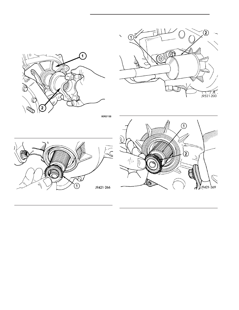
(5) Remove yoke from output shaft (Fig. 95). Use

puller C-452 if flange can not be removed by hand.

(6) Remove yoke rubber seal from front output

shaft (Fig. 96).

(7) Remove front output shaft seal with suitable

pry tool, or a slide hammer mounted screw.

INSTALLATION

(1) Install new front output seal in front case with

Installer Tool 9041 and Handle C-4171 (Fig. 97).

(2) Install yoke seal on front output shaft (Fig. 98).

Fig. 95 Front Yoke Removal

1 - TRANSFER CASE
2 - FRONT YOKE

Fig. 96 Yoke Seal Removal

1 - FLANGE SEAL

Fig. 97 Front Output Seal Installation - Typical

1 - SPECIAL TOOL C-4171
2 - SPECIAL TOOL 9041

Fig. 98 Installing Flange Seal On Front Shaft

1 - FRONT OUTPUT SHAFT
2 - FLANGE SEAL

21 - 230

TRANSFER CASE - NV241

TJ

FRONT OUTPUT SHAFT SEAL (Continued)

(3) Install yoke on front output shaft (Fig. 99).

Install a new yoke nut onto the front output shaft.

(4) Using Spanner Wrench 6958 (Fig. 100), tighten

the yoke nut to 176-271 N·m (130-200 ft. lbs.) torque.

(5) Install propeller shaft. (Refer to 3 - DIFFER-

ENTIAL & DRIVELINE/PROPELLER SHAFT/PRO-
PELLER SHAFT - INSTALLATION)

POSITION SENSOR

DESCRIPTION

The transfer case position sensor is an electronic

device whose output can be interpreted to indicate

the transfer case’s current operating mode. The sen-
sor consists of a five position, resistive multiplexed
circuit which returns a specific resistance value to
the Powertrain Control Module (PCM) for each trans-
fer case operating mode. The sensor is located on the
top of the transfer case, just left of the transfer case
centerline and rides against the sector plate rooster-
comb. The PCM supplies 5VDC (+/- 0.5V) to the sen-
sor and monitors the return voltage to determine the
sector plate, and therefore the transfer case, position.

OPERATION

OPERATING MODE VERSUS RESISTANCE

SENSOR POSITION

OPERATING MODE

SENSOR RESISTANCE (ohms)

1

2H

1124-1243

2

4H

650-719

3

NEUTRAL

389-431

4

4L

199-221

5

NOT USED

57-64

During normal vehicle operation, the Powertrain

Control Module (PCM) monitors the transfer case
position sensor return voltage to determine the oper-
ating mode of the transfer case. Refer to the Operat-
ing Mode Versus Resistance table for the correct
resistance (1-6) (Fig. 101) for each position.

REMOVAL

(1) Raise and support the vehicle.

(2) Disengage the transfer case position sensor

connector from the position sensor.

(3) Remove the position sensor from the transfer

case.

INSTALLATION

(1) Inspect the o-ring seal on the transfer case

position sensor. Replace the o-ring if necessary.

Fig. 99 Front Yoke Installation

1 - TRANSFER CASE
2 - FRONT YOKE

Fig. 100 Front Yoke Nut Installation

1 - TRANSFER CASE
2 - HOLDER 6958
3 - FRONT YOKE

TJ

TRANSFER CASE - NV241

21 - 231

FRONT OUTPUT SHAFT SEAL (Continued)

(2) Install the transfer case position sensor into

the transfer case. Torque the sensor to 20-34 N·m
(15-25 ft.lbs.).

(3) Engage the transfer case position sensor con-

nector to the position sensor.

(4) Lower vehicle.
(5) Verify proper sensor operation.

SHIFT LEVER

REMOVAL

(1) Shift transfer case into 4L.
(2) Raise vehicle.
(3) Loosen adjusting trunnion locknut and slide

shift rod out of trunnion (Fig. 102). If rod lacks
enough travel to come out of trunnion, push trunnion
out of torque shaft.

(4) Lower vehicle.
(5) Remove console. (Refer to 23 - BODY/INTERI-

OR/FLOOR CONSOLE - REMOVAL)

Fig. 102 Shift Linkage

1 - Rivnut (4)

8 - Torque Shaft

2 - Shift Lever Assembly

9 - Transfer Case Shift Lever

3 - Floorpan

10 - Torque Shaft Transfer Case Bracket

4 - Trunnion Lock Bolt

A - 3-4 N·m (27-35 in. lbs.)

5 - Selector Rod and Trunnion

B - 11-14 N·m (97-123 in. lbs.)

6 - Shift Lever Rod

C - 8-14 N·m (72-120 in. lbs.)

7 - Torque Shaft Frame Bracket

Fig. 101 Position Sensor Linear Movement

1 - POSITION 1 - 10mm ±0.5mm
2 - POSITION 2 - 12mm ±0.5mm
3 - POSITION 3 - 14mm ±0.5mm
4 - POSITION 4 - 16mm ±0.5mm
5 - POSITION 5 - 18mm ±0.5mm
6 - POSITION 6 - 20mm±0.5mm - FULL EXTENSION

21 - 232

TRANSFER CASE - NV241

TJ

POSITION SENSOR (Continued)

(6) Remove screws attaching lever assembly to

floorpan and remove assembly and shift rod (if left
attached).

INSTALLATION

(1) If shift rod was not removed from lever assem-

bly, work rod down through floorpan opening. Then
position lever assembly on floorpan and install
assembly attaching screws.

(2) Install console. (Refer to 23 - BODY/INTERI-

OR/FLOOR CONSOLE - INSTALLATION)

(3) Raise vehicle.
(4) Connect trunnion to torque shaft arm. Or, slide

shift rod into trunnion on range lever. Be sure shift
rod slides freely in trunnion.

(5) Verify that range lever is in 4L position. Then

tighten trunnion lock bolt.

(6) Lower vehicle and check transfer case shift

operation.

ADJUSTMENTS - SHIFT LINKAGE

(1) Shift transfer case into 4L position.
(2) Raise vehicle.
(3) Loosen lock bolt on adjusting trunnion (Fig.

103).

(4) Be sure linkage rod slides freely in trunnion.

Clean rod and apply spray lube if necessary.

(5) Verify that transfer case range lever is fully

engaged in 4L position.

(6) Tighten adjusting trunnion lock bolt.
(7) Lower vehicle.

VEHICLE SPEED SENSOR

DESCRIPTION

The 3-wire Vehicle Speed Sensor (VSS) (Fig. 104) is

located in the transfer case rear extension.

OPERATION

The VSS is a 3-circuit (3–wire), magnetic, hall-ef-

fect sensor.

The 3 circuits are:
• A 5-volt power supply from the Powertrain Con-

trol Module (PCM).

• A ground is provided for the sensor though a

low-noise sensor return circuit in the PCM.

• An input to the PCM is used to determine vehi-

cle speed and distance traveled.

The speed sensor generates 8 pulses per sensor

revolution. These signals, in conjunction with a
closed throttle signal from the throttle position sen-
sor, indicate a closed throttle deceleration to the
PCM. When the vehicle is stopped at idle, a closed
throttle signal is received by the PCM (but a speed
sensor signal is not received).

Fig. 103 Shift Linkage

1 - TRANSFER CASE SHIFT LEVER SHAFT
2 - SEAL
3 - TRANSFER CASE SHIFT LEVER ASSEMBLY
4 - FLOORPAN
5 - TRUNNION LOCK BOLT
6 - SHIFT ROD
7 - ADJUSTING TRUNNION
8 - TORQUE SHAFT BRACKET
9 - RANGE LEVER
10 - TORQUE SHAFT ROD
11 - TORQUE SHAFT
12 - LINKAGE BRACKET

Fig. 104 Speedometer Sensor

1 - EXTENSION HOUSING
2 - SPEEDOMETER SENSOR

TJ

TRANSFER CASE - NV241

21 - 233

SHIFT LEVER (Continued)


Content   ..  533  534  535  536   ..