Jeep Wrangler TJ. Manual - part 428


  Index      Jeep     Jeep Wrangler TJ - service repair manual 2005 year


Search            


Content   ..  426  427  428  429   ..


Jeep Wrangler TJ. Manual - part 428


STANDARD PROCEDURE - CAMSHAFT
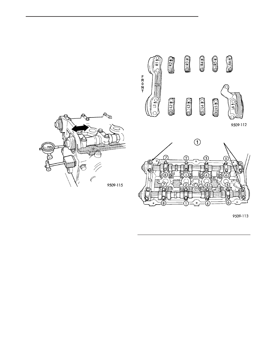
END-PLAY

(1) Oil camshaft journals and install camshaft

WITHOUT cam follower assemblies. Install rear cam
caps and tighten screws to specified torque.

(2) Using a suitable tool, move camshaft as far

rearward as it will go.

(3) Zero dial indicator (Fig. 18).
(4) Move camshaft as far forward as it will go.
(5) Record reading on dial indicator. For end play

specification, (Refer to 9 - ENGINE - SPECIFICA-
TIONS).

(6) If end play is excessive, check cylinder head

and camshaft for wear; replace as necessary.

REMOVAL

(1) Remove cylinder head cover. (Refer to 9 -

ENGINE/CYLINDER

HEAD/CYLINDER

HEAD

COVER(S) - REMOVAL)

(2) Remove camshaft position sensor and camshaft

target magnet. (Refer to 8 - ELECTRICAL/IGNI-
TION CONTROL/CAMSHAFT POSITION SENSOR -
REMOVAL)

(3) Remove timing belt. (Refer to 9 - ENGINE/

VALVE

TIMING/TIMING

BELT/CHAIN

AND

SPROCKETS - REMOVAL)

(4) Remove camshaft sprockets and timing belt

rear cover. (Refer to 9 - ENGINE/VALVE TIMING/
TIMING BELT / CHAIN COVER(S) - REMOVAL)

(5) Bearing

caps

are

identified

for

location.

Remove the outside bearing caps first (Fig. 19).

(6)

Loosen the camshaft bearing cap attaching

fasteners in sequence shown (Fig. 20) one camshaft
at a time.

CAUTION: Camshafts are not interchangeable. The
intake cam number 6 thrust bearing face spacing is
wider.

(7) Identify the camshafts before removing from

the head. The camshafts are not interchangeable.

(8) Remove camshafts from cylinder head.

NOTE: If removing rocker arms, identify for reinstal-
lation in the original position.

CLEANING

Clean camshaft with a suitable solvent.

INSPECTION

(1) Inspect camshaft bearing journals for damage

and binding (Fig. 21). If journals are binding, check
the cylinder head for damage. Also check cylinder
head oil holes for clogging.

(2) Check the cam lobe and bearing surfaces for

abnormal wear and damage. Replace camshaft if
defective.

NOTE: If camshaft is replaced due to lobe wear or
damage, always replace the rocker arms.

(3) Measure the lobe actual wear (unworn area -

wear zone = actual wear) (Fig. 21) and replace cam-

Fig. 18 Camshaft End Play - Typical

Fig. 19 Camshaft Bearing Cap Identification

Fig. 20 Camshaft Bearing Cap - Removal

1 - REMOVE OUTSIDE BEARING CAPS FIRST

TJ

ENGINE 2.4L

9 - 27

CAMSHAFT(S) (Continued)

shaft if out of limit. Standard value is 0.0254 mm
(0.001 in.), wear limit is 0.254 mm (0.010 in.).

INSTALLATION

CAUTION: Ensure that NONE of the pistons are at
top dead center when installing the camshafts.

(1) Lubricate all camshaft bearing journals, rocker

arms and camshaft lobes.

(2) Install all rocker arms in original positions, if

reused.

(3) Position camshafts on cylinder head bearing

journals. Install right and left camshaft bearing caps
No. 2 – 5 and right No. 6. Tighten M6 fasteners to 12
N·m (105 in. lbs.) in sequence shown in (Fig. 22).

(4) Apply Mopar

t Gasket Maker to No. 1 and No.

6 bearing caps (Fig. 23). Install bearing caps and
tighten M8 fasteners to 28 N·m (250 in. lbs.).

NOTE: Bearing end caps must be installed before
seals can be installed.

(5) Install

camshaft

oil

seals.

(Refer

to

9

-

ENGINE/CYLINDER

HEAD/CAMSHAFT

OIL

SEAL(S) - INSTALLATION)

(6) Install camshaft target magnet and camshaft

position sensor.

(7) Install cylinder head cover. (Refer to 9 -

ENGINE/CYLINDER

HEAD/CYLINDER

HEAD

COVER(S) - INSTALLATION)

(8) Install timing belt rear cover and camshaft

sprocket. (Refer to 9 - ENGINE/VALVE TIMING/
TIMING BELT / CHAIN COVER(S) - INSTALLA-
TION)

(9) Install timing belt. (Refer to 9 - ENGINE/

VALVE

TIMING/TIMING

BELT/CHAIN

AND

SPROCKETS - INSTALLATION)

CYLINDER HEAD COVER

REMOVAL

(1) Remove

intake

manifold.

(Refer

to

9

-

ENGINE/MANIFOLDS/INTAKE

MANIFOLD

-

REMOVAL)

(2) Remove ignition coil and spark plug wires.
(3) Disconnect PCV and make-up air hoses from

cylinder head cover.

(4) Remove cylinder head cover bolts.
(5) Remove cylinder head cover from cylinder

head.

CLEANING

Clean cylinder head and cover mating surfaces

using a suitable solvent.

INSPECTION

Inspect cover rails for flatness.

Fig. 21 Checking Camshaft(s) for Wear

1 - UNWORN AREA
2 - ACTUAL WEAR
3 - BEARING JOURNAL
4 - LOBE
5 - WEAR ZONE

Fig. 22 Camshaft Bearing Cap Tightening Sequence

Fig. 23 Camshaft Bearing Cap Sealing

1 - 1.5 mm (.060 in.) DIAMETER BEAD OF MOPAR GASKET
MAKER

9 - 28

ENGINE 2.4L

TJ

CAMSHAFT(S) (Continued)

INSTALLATION

NOTE: Replace spark plug well seals and bolt
assemblies when installing a new cylinder head
cover gasket.

(1) Install new cylinder head cover gaskets and

spark plug well seals (Fig. 24).

(2) Replace cylinder head cover bolt assemblies

(Fig. 25).

CAUTION: Do not allow oil or solvents to contact
the timing belt as they can deteriorate the rubber
and cause tooth skipping.

(3)

Apply Mopar

t Engine RTV GEN II at the

camshaft cap corners and at the top edges of the 1/2
round seal (Fig. 26).

Fig. 24 Spark Plug Well Seals

Fig. 25 Cylinder Head Cover Bolt Assembly

Fig. 26 Sealer Locations - Typical

1 – SEALER LOCATION

TJ

ENGINE 2.4L

9 - 29

CYLINDER HEAD COVER (Continued)

(4)

Install cylinder head cover assembly to cylin-

der head. Install all bolts, ensuring the two (2) bolts
containing the sealing washer are located in the cen-
ter locations of cover. Tighten bolts in sequence
shown in (Fig. 27). Using a 3 step torque method as
follows:

(a) Tighten all bolts to 4.5 N·m (40 in. lbs.).
(b) Tighten all bolts to 9.0 N·m (80 in. lbs.).
(c) Tighten all bolts to 12 N·m (105 in. lbs.).

(5) Install intake manifold.
(6) Install ignition coil and spark plug wires.

Tighten fasteners to 12 N·m (105 in. lbs.).

(7) If the PCV valve was removed, apply Mopar

t

Thread Sealant with Teflon to threads and install
valve to cylinder head cover. Tighten PCV valve to 8
N·m (70 in. lbs.).

(8) Connect PCV and make-up air hoses to cylin-

der head cover.

INTAKE/EXHAUST VALVES &
SEATS

DESCRIPTION

The four valves per cylinder are opened by using

roller rocker arms which pivot on hydraulic lash adjust-
ers. The valves have chrome plated valve stems. Viton
rubber valve stem seals are integral with the spring
seats. They have chrome plated stems to prevent scuff-
ing. Viton rubber valve stem seals are integral with the
spring seats. The valves, spring retainers,and locks, are
the 3 - bead lock design

CLEANING

(1) Clean

all

valves

thoroughly

and

discard

burned, warped and cracked valves.

VALVE SPRINGS

REMOVAL

REMOVAL - CYLINDER HEAD ON

(1) Remove camshafts.
(2) Rotate crankshaft until piston is at TDC on

compression.

(3) With air hose attached to adapter tool installed

in spark plug hole, apply 90-120 psi air pressure.

(4) Using Special Tool MD-998772-A with adapter

6779 (Fig. 28), compress valve springs and remove
valve locks.

(5) Remove valve spring(s).
(6) Remove valve stem seal(s) by a using valve

stem seal tool (Fig. 30).

REMOVAL - CYLINDER HEAD OFF

(1) With cylinder head removed from cylinder

block, compress valve springs using a universal valve
spring compressor.

(2) Remove valve retaining locks, valve spring

retainers, valve stem seals and valve springs.

(3) Before removing valves, remove any burrs

from valve stem lock grooves to prevent dam-
age to the valve guides. 
Identify valves, locks and
retainers to insure installation in original location.

(4) Inspect the valves. (Refer to 9 - ENGINE/CYL-

INDER HEAD/VALVE SPRINGS - INSPECTION)

Fig. 27 CYLINDER HEAD TIGHTENING SEQUENCE

Fig. 28 Valve Spring - Removal/Installation

1 - VALVE SPRING COMPRESSOR MD 998772A
2 - AIR HOSE

9 - 30

ENGINE 2.4L

TJ

CYLINDER HEAD COVER (Continued)


Content   ..  426  427  428  429   ..