Jeep Liberty KJ. Manual - part 193


  Index      Jeep     Jeep Liberty KJ - service repair manual 2006 year


Search            


Content   ..  191  192  193  194   ..


Jeep Liberty KJ. Manual - part 193


5.

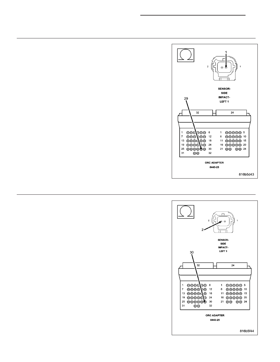
CHECK THE (R15) LEFT SIDE IMPACT SENSOR 1 GROUND CIRCUIT FOR AN OPEN OR HIGH
RESISTANCE

Connect the 8443 Load Tool ORC Adaptor to the ORC connector.

Measure the resistance of the (R15) Left Side Impact Sensor 1 Ground
circuit between the Left Side Impact Sensor 1 connector and the 8443
Load Tool ORC Adaptor.

Is the resistance below 1.0 ohm?

Yes

>> Go To 6

No

>> Repair the (R15) Left Side Impact Sensor 1 Ground circuit

for an open or high resistance.

Perform *AIRBAG SYSTEM VERIFICATION TEST - VER 1.

6.

CHECK THE (R13) LEFT SIDE IMPACT SENSOR 1 CIRCUIT FOR AN OPEN OR HIGH RESISTANCE

Measure the resistance of the (R13) Left Side Impact Sensor 1 Signal
circuit between the Left Side Impact Sensor 1 connector and the 8443
Load Tool ORC Adaptor.

Is the resistance below 1.0 ohm?

Yes

>> Go To 7

No

>> Repair the (R13) Left Side Impact Sensor 1 Signal circuit

for an open or high resistance.

Perform *AIRBAG SYSTEM VERIFICATION TEST - VER 1.

8O - 78

RESTRAINTS - ELECTRICAL DIAGNOSTICS

KJ

7.

CHECK THE LEFT SIDE IMPACT SENSOR 1 OPERATION

Replace the Left Side Impact Sensor 1 in accordance with the Service Information.

Remove any special tools or jumper wires and reconnect all previously disconnected components, except the bat-
tery.

WARNING: To avoid personal injury or death, turn the ignition on, then reconnect the battery.
With the scan tool, erase all Airbag System Module DTCs.

Turn the Ignition Off, wait 15 seconds, then turn the Ignition On. Wait one minute before proceeding.

With the scan tool, read active ORC DTCs.

Does the scan tool display: LEFT SIDE IMPACT SENSOR 1 INTERNAL 1?

Yes

>>

WARNING: If the Occupant Restraint Controller (ORC) is dropped at any time, it must be replaced. Failure to
take the proper precautions could result in accidental airbag deployment and personal injury or death.

WARNING: To avoid personal injury or death, turn the ignition off, disconnect the battery and wait two min-
utes before proceeding.

Replace the ORC in accordance with Service Instructions.

Perform AIRBAG SYSTEM VERIFICATION TEST - VER 1.

No

>> Perform *AIRBAG SYSTEM VERIFICATION TEST - VER 1.

8.

CHECKING STORED OR INTERMITTENT CODES

NOTE: Diagnose and repair all active codes before diagnosing stored codes. Refer to the Table of Contents
in this Section for a complete list of airbag system diagnostic procedures.
With the scan tool, record and erase all Airbag System Module DTCs.

WARNING: To avoid personal injury or death, turn the ignition off, disconnect the battery and wait two min-
utes before proceeding.
Using the wiring diagram/schematic as a guide, inspect the related wiring and connectors for chafed, pierced,
pinched, and partially broken wires, and for broken, bent, pushed out, corroded, and contaminated terminals. Repair
as necessary.

Reconnect all disconnected components and harness connectors.

WARNING: To avoid personal injury or death, turn the ignition on, then reconnect the battery.
With the scan tool, monitor for active codes while performing the following:

Wiggle the wiring harness and connectors of the related airbag circuit.

Continue the test until either a code becomes active or the problem area is isolated.

In the previous steps you have attempted to recreate the conditions responsible for setting the DTC in question /
causing the intermittent condition.

Are any ACTIVE DTCs present?

Yes

>> Select the appropriate diagnostic procedure from the Table of Contents in this section.

No

>> No problem found at this time. Erase all codes before returning the vehicle to the customer.

KJ

RESTRAINTS - ELECTRICAL DIAGNOSTICS

8O - 79

LOSS OF IGNITION RUN - START

8O - 80

RESTRAINTS - ELECTRICAL DIAGNOSTICS

KJ

For a complete wiring diagram Refer to Section 8W.

When Monitored:
With the ignition in the Run-Start position.

Set Condition:
The Occupant Restraint Controller (ORC) monitors the voltage of the (F201) Fused Ignition Switch Output
(Run-Start) circuit and will set this DTC if it drops below approximately 4.5 volts. Note: this condition will also
cause a No Response from the Occupant Classification module (OCM).

Possible Causes

(F201) FUSED IGNITION SWITCH OUTPUT (RUN-START) SHORTED TO GROUND

(F201) FUSED IGNITION SWITCH OUTPUT (RUN-START) CIRCUIT OPEN

(F944) IGNITION SWITCH OUTPUT CIRCUIT OPEN

JUNCTION BLOCK 36 AIRBAG RUN-START CIRCUIT FUSE OPEN

OCCUPANT CLASSIFICATION MODULE (OCM)

OCCUPANT RESTRAINT CONTROLLER (ORC)

Diagnostic Test

1.

DETERMINE ACTIVE OR STORED DTC

NOTE: Ensure that the battery is fully charged.
Turn the ignition on.

Select ACTIVE or STORED DTC:

ACTIVE ORC DTC

Go To 2

STORED ORC DTC

Go To 10

2.

CHECK THE AIRBAG RUN-START CIRCUIT FUSE

Turn the ignition off.

Remove and inspect the Airbag Run-Start circuit fuse.

NOTE: Check connectors - Clean and repair as necessary.

Is the fuse open?

Yes

>> Go To 3

No

>> Go To 8

KJ

RESTRAINTS - ELECTRICAL DIAGNOSTICS

8O - 81


Content   ..  191  192  193  194   ..