Jeep Liberty KJ. Manual - part 194


  Index      Jeep     Jeep Liberty KJ - service repair manual 2006 year


Search            


Content   ..  192  193  194  195   ..


Jeep Liberty KJ. Manual - part 194


3.

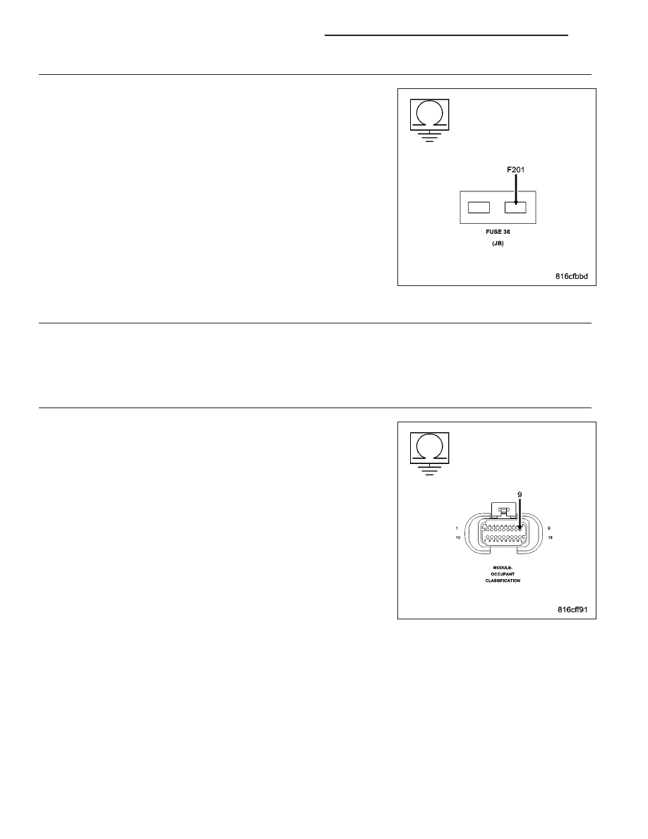
CHECK FOR A SHORTED (F201) FUSED IGNITION SWITCH OUTPUT (RUN-START) CIRCUIT

WARNING: To avoid personal injury or death, turn the ignition off,
disconnect the battery and wait two minutes before proceeding.
Measure the resistance of the (F201) Fused Ignition Switch Output
(Run-Start) circuit between ground and the Airbag Run-Start fuse termi-
nal (output side).

Is the resistance below 100.0 ohms?

Yes

>> Go To 4

No

>> Using the wiring diagram/schematic as a guide, inspect the

related wiring and connectors. Look for chafed, pierced,
pinched, or partially broken wires and broken, bent, pushed
out, spread, corroded, or contaminated terminals. Replace
the Airbag Run-Start circuit fuse.

Perform *AIRBAG SYSTEM VERIFICATION TEST - VER 1.

4.

CHECKING EQUIPMENT

Is the vehicle equipped with an Occupant Classification System?

Yes

>> Go To 5

No

>> Go To 6

5.

CHECK THE OCCUPANT CLASSIFICATION MODULE (OCM) FOR A SHORT TO GROUND

Disconnect the OCM harness connector.

NOTE: Check connectors - Clean and repair as necessary.
Measure the resistance of the (F201) Fused Ignition Switch Output
(Run-Start) circuit between ground and the Airbag Run-Start fuse termi-
nal (output side).

Is the resistance below 100.0 ohms?

Yes

>> Go To 6

No

>> Go To 7

8O - 82

RESTRAINTS - ELECTRICAL DIAGNOSTICS

KJ

6.

CHECK THE OCCUPANT RESTRAINT CONTROLLER (ORC) FOR A SHORT TO GROUND

Disconnect the ORC C1 and C2 connectors.

NOTE: Check connectors - Clean and repair as necessary.
Connect the Load Tool ORC 8443–25 Adaptor to the ORC C2 connec-
tor.

Measure the resistance of the (F201) Fused Ignition Switch Output
(Run-Start) circuit.

Is the resistance below 100.0 ohms?

Yes

>> Repair the (F201) Fused Ignition Switch Output (Run-Start)

circuit for a short to ground. Replace the Airbag Run-Start
circuit fuse.

Perform *AIRBAG SYSTEM VERIFICATION TEST - VER 1.

No

>>

WARNING: If the Occupant Restraint Controller (ORC) is dropped
at any time, it must be replaced. Failure to take the proper precau-
tions could result in accidental airbag deployment and personal
injury or death.

WARNING: To avoid personal injury or death, turn the ignition off, disconnect the battery and wait two min-
utes before proceeding.

Replace the ORC in accordance with the Service Information. Replace the Airbag Run-Start circuit fuse.

Perform *AIRBAG SYSTEM VERIFICATION TEST - VER 1.

7.

DETERMINE THE CORRECT REPAIR

NOTE: The Occupant Classification Module (OCM) and the Passenger Seat Bladder and Cushion Kit are the
only serviceable OCS components.
Determine the correct repair by verifying if the front passenger seat has a Bladder and Cushion Service Kit as
follows:

If possible, check the vehicle’s repair history.

The Service Kit wiring harness uses tamper resistant material on the harness connector. Inspect for the tamper
resistant material on the harness connector.

Does the seat have a Bladder and Cushion Service Kit?

Yes

>>

WARNING: If the Occupant Classification Module (OCM) is dropped at any time, it must be replaced. Failure
to take the proper precautions could result in accidental airbag deployment and personal injury or death.

WARNING: To avoid personal injury or death, turn the ignition off, disconnect the battery and wait two min-
utes before proceeding.

NOTE: The Bladder and Cushion Kit are calibrated as an assembly. Do not disconnect the Bladder from the
Cushion Kit. Service only as an assembly.
Replace OCS Bladder and Cushion Kit in accordance with the Service information.

Perform SYSTEM VERIFICATION REQUIRED test.

Perform *AIRBAG SYSTEM VERIFICATION TEST - VER 1.

No

>>

WARNING: If the Occupant Classification Module (OCM) is dropped at any time, it must be replaced. Failure
to take the proper precautions could result in accidental airbag deployment and personal injury or death.

WARNING: To avoid personal injury or death, turn the ignition off, disconnect the battery and wait two min-
utes before proceeding.

Replace the OCM in accordance with the Service Information.

Perform SYSTEM VERIFICATION REQUIRED test.

Perform *AIRBAG SYSTEM VERIFICATION TEST - VER 1.

JB F201 OHM OUTPUT R ST

KJ

RESTRAINTS - ELECTRICAL DIAGNOSTICS

8O - 83

8.

CHECK THE (F944) IGNITION SWITCH OUTPUT CIRCUIT FOR AN OPEN

Turn the ignition on.

Measure the voltage of the (F944) Ignition Switch Output circuit at the
Airbag Run-Start circuit fuse terminal (input side).

NOTE: Reinstall the fuse after performing this test.

Is the voltage above 4.5 volts?

Yes

>> Go To 9

No

>> Repair the (F944) Ignition Switch Output circuit for an open.

Reinstall the Airbag Run-Start circuit fuse.

Perform *AIRBAG SYSTEM VERIFICATION TEST - VER 1.

9.

CHECK THE (F201) FUSED IGNITION SWITCH OUTPUT (RUN-START) CIRCUIT FOR AN OPEN

WARNING: To avoid personal injury or death, turn the ignition off,
disconnect the battery and wait two minutes before proceeding.
Disconnect the ORC C1 and C2 connector.

NOTE: Check connectors - Clean and repair as necessary.

NOTE: If not done so previously, reinstall the Airbag Run-Start cir-
cuit fuse.
Connect the appropriate Load Tool Adaptor to the ORC C2 connectors.

WARNING: To avoid personal injury or death, turn the ignition on,
then reconnect the battery.
Measure the voltage of the (F201) Fused Ignition Switch Output (Run-
Start) Circuit.

Is the voltage above 4.5 volts?

Yes

>>

WARNING: To avoid personal injury or death, turn the ignition off,
disconnect the battery and wait two minutes before proceeding.

WARNING: If the Occupant Restraint Controller is dropped at any time, it must be replaced. Failure to take
the proper precautions could result in accidental airbag deployment and personal injury or death.

NOTE: When reconnecting Airbag System components the Ignition must be turned off and the Battery must
be disconnected.

Replace the ORC in accordance with the Service Information.

Perform *AIRBAG SYSTEM VERIFICATION TEST - VER 1.

No

>> Repair (F201) Fused Ignition Switch Output (Run-Start) circuit for an open.

Perform *AIRBAG SYSTEM VERIFICATION TEST - VER 1.

JB F944 VOLTS INPUT R ST

8O - 84

RESTRAINTS - ELECTRICAL DIAGNOSTICS

KJ

10.

CHECKING STORED OR INTERMITTENT CODES

NOTE: Diagnose and repair all active codes before diagnosing stored codes. Refer to the Table of Contents
in this Section for a complete list of airbag system diagnostic procedures.
With the scan tool, record and erase all Airbag System Module DTCs.

WARNING: To avoid personal injury or death, turn the ignition off, disconnect the battery and wait two min-
utes before proceeding.
Using the wiring diagram/schematic as a guide, inspect the related wiring and connectors for chafed, pierced,
pinched, and partially broken wires, and for broken, bent, pushed out, corroded, and contaminated terminals. Repair
as necessary.

Reconnect all disconnected components and harness connectors.

WARNING: To avoid personal injury or death, turn the ignition on, then reconnect the battery.
With the scan tool, monitor for active codes while performing the following:

Wiggle the wiring harness and connectors of the related airbag circuit.

Continue the test until either a code becomes active or the problem area is isolated.

In the previous steps you have attempted to recreate the conditions responsible for setting the DTC in question /
causing the intermittent condition.

Are any ACTIVE DTCs present?

Yes

>> Select the appropriate diagnostic procedure from the Table of Contents in this section.

No

>> No problem found at this time. Erase all codes before returning the vehicle to the customer.

KJ

RESTRAINTS - ELECTRICAL DIAGNOSTICS

8O - 85


Content   ..  192  193  194  195   ..