Content .. 1422 1423 1424 1425 ..
Jeep Liberty KJ. Manual - part 1424
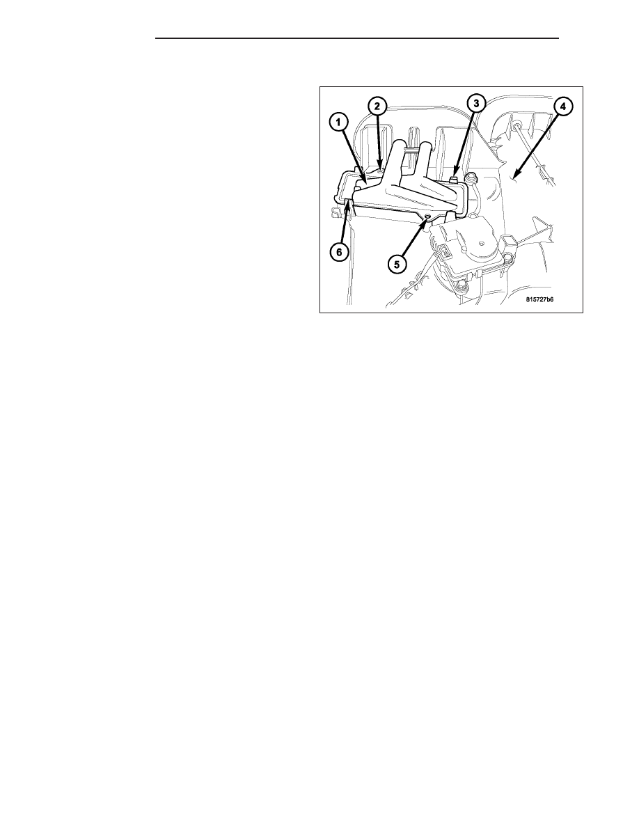
INSTALLATION
NOTE: Make sure that the foam insulator is prop-
erly positioned in the HVAC housing.
1. Carefully install the heater core (1) into the top of
the HVAC housing (4).
2. Engage the four retaining tabs (3 and 6) that
secure the heater core to the HVAC housing.
3. If equipped, install the two screws (2 and 5) that
secure the heater core to the HVAC housing.
Tighten the screws to 2 N·m (17 in. lbs.).
NOTE: If the heater core is being replaced, flush
the cooling system (Refer to 7 - COOLING - STAN-
DARD PROCEDURE - COOLING SYSTEM CLEAN-
ING/REVERSE FLUSHING).
4. Install the HVAC housing (Refer to 24 - HEATING
& AIR CONDITIONING/DISTRIBUTION/HOUSING-
HVAC - INSTALLATION).
24 - 98
PLUMBING
KJ