Content .. 1421 1422 1423 1424 ..
Jeep Liberty KJ. Manual - part 1423
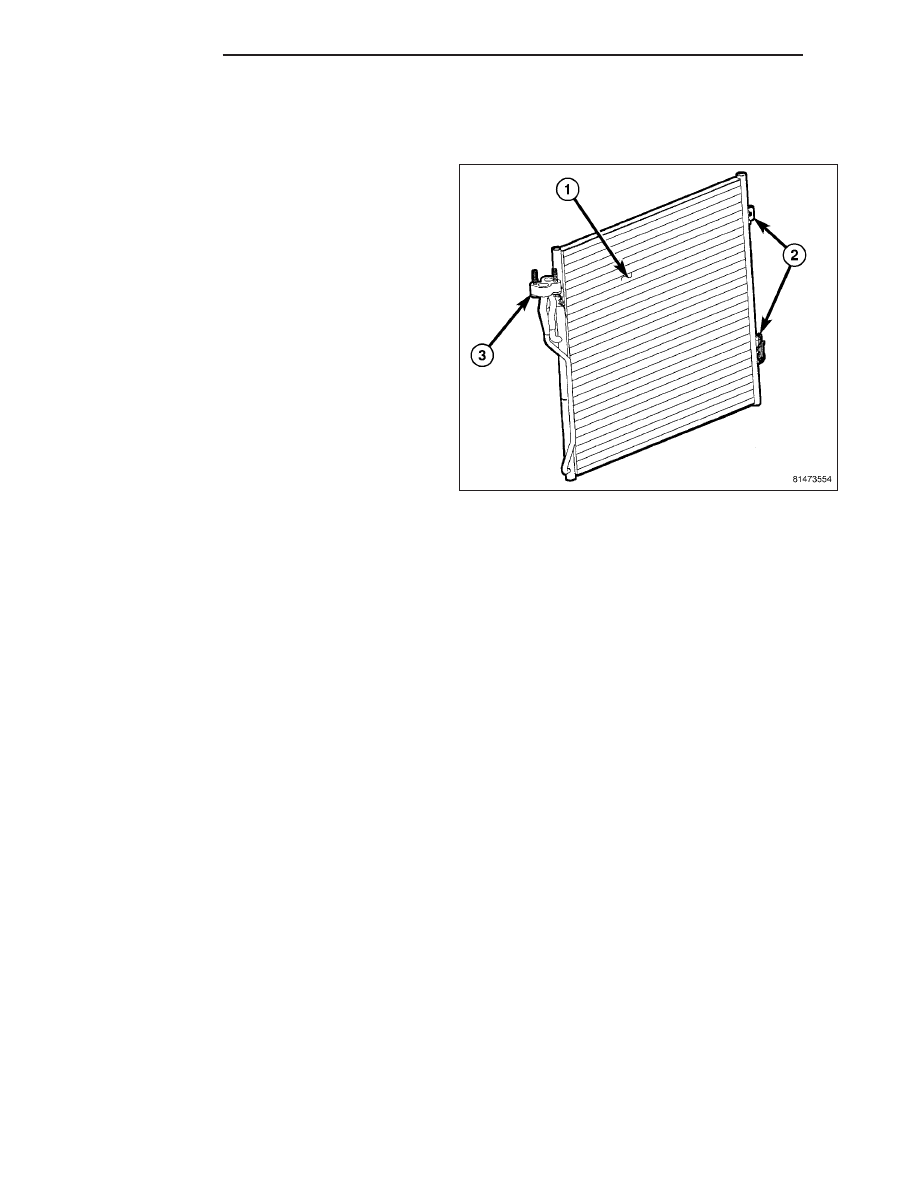
CONDENSER-A/C
DESCRIPTION
The A/C condenser (1) is located in the front of the
engine compartment behind the grille. The A/C con-
denser is a heat exchanger that allows the high-pres-
sure refrigerant gas being discharged by the A/C
compressor to give up its heat to the air passing over
the condenser fins, which causes the refrigerant to
cool and change to a liquid state.
The A/C condenser is equipped with mounting provi-
sions (2) and a tapping block (3) for the A/C refriger-
ant lines.
OPERATION
When air passes through the fins of the A/C condenser, the high-pressure refrigerant gas within the A/C condenser
gives up its heat. The refrigerant then condenses as it leaves the A/C condenser and becomes a high-pressure
liquid. The volume of air flowing over the condenser fins is critical to the proper cooling performance of the A/C
system. Therefore, it is important that there are no objects placed in front of the radiator grille openings at the front
of the vehicle or foreign material on the condenser fins that might obstruct proper air flow. Also, any factory-installed
air seals or shrouds must be properly reinstalled following radiator or A/C condenser service.
The A/C condenser cannot be repaired and, if faulty or damaged, it must be replaced.
REMOVAL
WARNING: Refer to the applicable warnings and cautions for this system before performing the following
operation (Refer to 24 - HEATING & AIR CONDITIONING/PLUMBING - WARNINGS) and (Refer to 24 - HEAT-
ING & AIR CONDITIONING/PLUMBING - CAUTIONS). Failure to follow the warnings and cautions could result
in possible personal injury or death.
CAUTION: Before removing the A/C condenser, note the location of each of the radiator/condenser air seals.
These air seals are used to direct air through the A/C condenser and radiator. The air seals must be rein-
stalled in their proper locations in order for the A/C and engine cooling systems to perform as designed.
24 - 94
PLUMBING
KJ