Jeep Liberty KJ. Manual - part 1418


  Index      Jeep     Jeep Liberty KJ - service repair manual 2006 year


Search            


Content   ..  1416  1417  1418  1419   ..


Jeep Liberty KJ. Manual - part 1418


INSTALLATION

NOTE: Failure to install the blower motor correctly could result in an air leak or the blower motor becoming
completely disengaged from the HVAC housing.

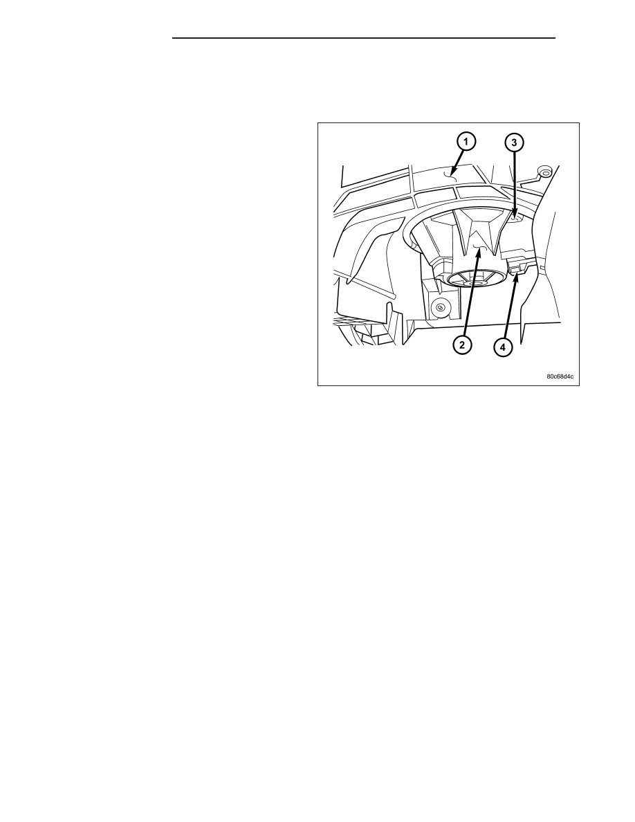
NOTE: LHD model shown in illustration. LHD
model similar.

1. Align and install the blower motor (2) into the

HVAC housing (1).

2. Rotate the blower motor until the locking tab (3)

secures the blower motor to the HVAC housing.

3. Connect the wire harness lead to the blower motor

connector (4).

4. Reconnect the negative battery cable.

5. Test the blower motor for proper installation by

operating the blower motor at its fastest speed
while checking around the outer edges of the
blower motor and HVAC housing for air leaks. If
any are found, remove and reinstall the blower
motor.

24 - 74

DISTRIBUTION

KJ

OUTLET-AIR

DESCRIPTION

There are two defroster air outlets (2) in the defroster
grille (3) located on the top of the instrument panel
(7). The airflow from the defroster outlets is directed
by fixed vanes in the defroster grille and cannot be
adjusted. The defroster air outlets are not serviceable
from the defroster grille (Refer to 23 - BODY/INSTRU-
MENT PANEL/DEFROSTER GRILLE - REMOVAL).

There are two side window demister air outlets (4).
One located at each end of the instrument panel near
the A-pillars. The airflow from the side window demis-
ter air outlets is directed by fixed vanes in the demis-
ter outlet grilles and cannot be adjusted. The side
window demister air outlet located at the right end of
the instrument panel is integral to the passenger side
air bag door (5) and cannot be serviced separately
(Refer to 8 - ELECTRICAL/RESTRAINTS/PASSEN-
GER AIRBAG - REMOVAL). The other side window
demister air outlet is integral to the instrument cluster
bezel (8) and cannot be serviced separately (Refer to
23 - BODY/INSTRUMENT PANEL/CLUSTER BEZEL - REMOVAL).

There are four instrument panel air outlets. One air outlet is located near each outboard end of the instrument panel
facing the rear of the vehicle and the other two outlets are located near the top of the instrument panel center bezel.
The air outlet located at the right end of the instrument panel is integral to the passenger side air bag door and
cannot be serviced separately (Refer to 8 - ELECTRICAL/RESTRAINTS/PASSENGER AIRBAG - REMOVAL). The
air outlets located at the center of the instrument panel are integral to the instrument panel and cannot be serviced
separately (Refer to 23 - BODY/INSTRUMENT PANEL/INSTRUMENT PANEL CENTER BEZEL - REMOVAL). The
other instrument panel air outlet is integral to the instrument cluster bezel (1) and cannot be serviced separately
(Refer to 23 - BODY/INSTRUMENT PANEL/IP PASSENGER SIDE BEZEL - REMOVAL).

Each of the instrument panel air outlets contain an air outlet barrel (6) that is used to direct or shut off the flow of
the conditioned air leaving the instrument panel.

CAUTION: The instrument panel air outlet barrels can only be installed in one direction. If the outlet barrel
is not properly oriented prior to installation, damage to the outlet barrel will occur.

NOTE: Each air outlet barrel is retained into the air outlet housing by two pivot shafts. One pivot shaft is
larger than the other. The air outlet barrel must be first installed onto the larger pivot shaft, then snapped
into place over the smaller pivot shaft.

All of the instrument panel air outlets barrels can be serviced individually.

REMOVAL

NOTE: The instrument panel air outlet barrels are retained onto the pivots located in the outlet housing by
a light snap fit.

KJ

DISTRIBUTION

24 - 75

1. Using a trim stick C-4755 or equivalent (1), gently

pry the panel air outlet barrel(s) (2) out of the
instrument panel air outlet(s) (3) as required.

INSTALLATION

CAUTION: The instrument panel air outlet barrels can only be installed in one direction. If the air outlet
barrel is not properly oriented prior to installation, damage to the air outlet barrel will occur.

NOTE: Each air outlet barrel is retained into the air outlet housing by two pivot shafts. One pivot shaft is
larger than the other. The air outlet barrel must be first installed onto the larger pivot shaft, then snapped
into place over the smaller pivot shaft.

1. Install the air outlet barrel (1) onto the larger pivot

shaft (2) located in the instrument panel air outlet
housing (3).

24 - 76

DISTRIBUTION

KJ

2. Gently push the air outlet barrel (1) onto the

smaller pivot shaft (2) of the instrument panel air
outlet housing (3) until it snaps into position.

KJ

DISTRIBUTION

24 - 77


Content   ..  1416  1417  1418  1419   ..