Content .. 1237 1238 1239 1240 ..
Jeep Liberty KJ. Manual - part 1239
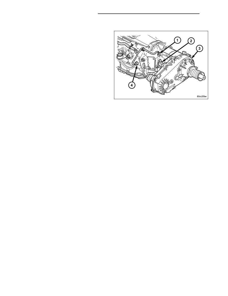
REMOVAL
1. Raise and support the vehicle.
2. Disengage the transfer case position sensor con-
nector from the position sensor (2).
3. Remove the position sensor from the transfer case.
INSTALLATION
1. Inspect the o-ring seal on the transfer case position sensor. Replace the o-ring if necessary.
2. Install the transfer case position sensor into the transfer case. Torque the sensor to 27 N·m (20 ft.lbs.).
3. Engage the transfer case position sensor connector to the position sensor.
4. Lower vehicle.
5. Verify proper sensor operation.
21 - 900
TRANSFER CASE - NV241 GENII
KJ