Jeep Liberty KJ. Manual - part 1238


  Index      Jeep     Jeep Liberty KJ - service repair manual 2006 year


Search            


Content   ..  1236  1237  1238  1239   ..


Jeep Liberty KJ. Manual - part 1238


SEAL-EXTENSION HOUSING

REMOVAL

1. Raise and support vehicle.

2. Remove rear propeller shaft. (Refer to 3 - DIFFERENTIAL & DRIVELINE/PROPELLER SHAFT/PROPELLER

SHAFT - REMOVAL)

3. Using a suitable pry tool or slide-hammer mounted screw, remove the extension housing seal.

INSTALLATION

1. Clean fluid residue from sealing surface and

inspect for defects.

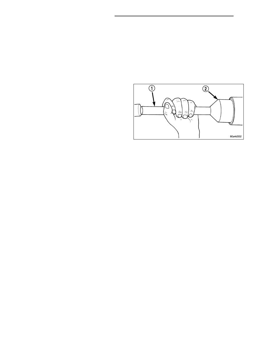
2. Using Seal Installer D-163 (2) and Universal Han-

dle C-4171 (1), install seal in extension housing.

3. Install propeller shaft. (Refer to 3 - DIFFERENTIAL

& DRIVELINE/PROPELLER SHAFT/PROPELLER
SHAFT - INSTALLATION)

4. Verify proper transfer case fluid level.

5. Lower vehicle.

21 - 896

TRANSFER CASE - NV241 GENII

KJ

FLUID

STANDARD PROCEDURE - FLUID DRAIN AND FILL

The fill (2) and drain (3) plugs are both in the rear
case. Correct fill level is to the bottom edge of the fill
plug hole. Be sure the vehicle is level to ensure an
accurate fluid level check.

KJ

TRANSFER CASE - NV241 GENII

21 - 897

SEAL-FRONT OUTPUT SHAFT

REMOVAL

1. Raise vehicle.

2. Remove front propeller shaft. (Refer to 3 - DIFFER-

ENTIAL & DRIVELINE/PROPELLER SHAFT/PRO-
PELLER SHAFT - REMOVAL)

3. Remove front output shaft companion flange.

4. Remove seal (1) from front case with pry tool (2).

INSTALLATION

1. Install new front output seal in front case (2) with

Installer Tool 6952-A (1) as follows:

a. Place new seal on tool. Garter spring on seal

goes toward interior of case.

b. Start seal in bore with light taps from hammer.

Once seal is started, continue tapping seal into
bore until installer tool seats against case.

2. Install the front output shaft companion flange.

Tighten the companion flange nut to 149 N·m (110
ft.lbs.).

3. Install the front propeller shaft. (Refer to 3 - DIF-

FERENTIAL & DRIVELINE/PROPELLER SHAFT/
PROPELLER SHAFT - INSTALLATION)

21 - 898

TRANSFER CASE - NV241 GENII

KJ

SENSOR-POSITION

DESCRIPTION

The transfer case position sensor (2) is an electronic
device whose output can be interpreted to indicate the
transfer case’s current operating mode. The sensor
consists of a five position, resistive multiplexed circuit
which returns a specific resistance value to the Pow-
ertrain Control Module (PCM) for each transfer case
operating mode. The sensor is located on the top of
the transfer case, just left of the transfer case center-
line and rides against the sector plate roostercomb.
The PCM supplies 5VDC (+/- 0.5V) to the sensor and
monitors the return voltage to determine the sector
plate, and therefore the transfer case, position.

OPERATION

During normal vehicle operation, the Powertrain Con-
trol Module (PCM) monitors the transfer case position
sensor return voltage to determine the operating mode
of the transfer case. Refer to the Operating Mode Ver-
sus Resistance table for the correct resistance for
each position.

Operating Mode Versus Resistance

SENSOR POSITION

OPERATING MODE

SENSOR RESISTANCE (ohms)

1

2WD

1124-1243

2

4WD PART TIME

650-719

3

4WD FULL TIME

389-431

4

NEUTRAL

199-221

5

4WD LOW

57-64

Position Sensor Linear Movement

1 - POSITION 1 - 10mm ±0.5mm
2 - POSITION 2 - 12mm ±0.5mm
3 - POSITION 3 - 14mm ±0.5mm
4 - POSITION 4 - 16mm ±0.5mm
5 - POSITION 5 - 18mm ±0.5mm
6 - POSITION 6 - 20mm±0.5mm - FULL EXTENSION

KJ

TRANSFER CASE - NV241 GENII

21 - 899


Content   ..  1236  1237  1238  1239   ..