Jeep Liberty KJ. Manual - part 1236


  Index      Jeep     Jeep Liberty KJ - service repair manual 2006 year


Search            


Content   ..  1234  1235  1236  1237   ..


Jeep Liberty KJ. Manual - part 1236


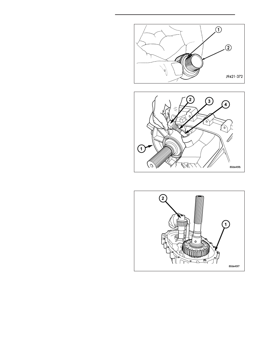
17. Install new o-ring on detent plug (2).

18. Install detent plunger (4), spring (3), and plug (2).

Tighten the plug to 16-25 N·m (12-18 ft. lbs.).

FRONT OUTPUT SHAFT AND DRIVE CHAIN

1. Install the front output shaft (2) into the front output

shaft bearing.

21 - 888

TRANSFER CASE - NV241 GENII

KJ

2. Insert front sprocket in drive chain.

3. Install drive chain (2) around mainshaft sprocket

(1). Then position front sprocket over front shaft.

4. Raise mainshaft about 2.54 cm (one inch) and seat

front sprocket on front output shaft.

5. If mainshaft and mode sleeve were unseated dur-

ing chain installation, align and reseat mainshaft in
input gear and hub.

6. Install front sprocket (1) retaining ring (2).

7. Install spring (2) and cup (1) on shift rail.

8. Insert magnet (1) in front case pocket (2).

KJ

TRANSFER CASE - NV241 GENII

21 - 889

OIL PUMP AND REAR CASE

CAUTION: Do not remove the bolts holding the oil
pump cover to the rear case half. The oil pump
cover is aligned to the rear output shaft inner
bearing race and will become mis-aligned if the
bolts are loosened. If the transfer case failure has
generated any debris which may have become
trapped in the oil pump. the rear case and oil
pump assembly MUST be replaced.

1. Apply bead of Mopar

T

Gasket Maker, or equivalent,

to mating surface of front case. Keep sealer bead
width to maximum of 3/16 inch. Do not use exces-
sive amount of sealer as excess will be displaced
into case interior.

2. Align oil pump with mainshaft and align shift rail

with bore in rear case. Then install rear case (1)
and oil pump assembly.

3. Install 4-5 rear case(1)-to front case (2) bolts to

hold rear case in position. Tighten bolts snug but
not to specified torque at this time.

CAUTION: Verify that shift rail, and case alignment
dowels are seated before installing any bolts.
Case could be cracked if shaft rail or dowels are
misaligned.

4. Apply Loctite™ 242 to remainder of rear case-to-

front case bolt threads and install bolts. Tighten
bolts to 20-27 N·m (15-24 ft. lbs.),

5. Install rear output bearing (2) snap-ring (3) to out-

put shaft.

21 - 890

TRANSFER CASE - NV241 GENII

KJ

REAR EXTENSION

1. Install new seal in rear extension housing seal with

Installer D-163 and Handle C-4171..

2. Apply bead of Mopar

T

Gasket Maker, or equivalent,

to mating surface of rear extension housing. Keep
sealer bead width to maximum of 3/16 inch. Do not
use excessive amount of sealer as excess could
be displaced into output bearing.

3. Align and install rear extension housing (1) on

retainer.

4. Apply Mopar

T

Silicone Sealer to threads of rear

extension housing bolts. Then install and tighten
bolts to 16-24 N·m (12-18 ft. lbs.) torque.

COMPANION FLANGE AND RANGE LEVER

1. Install range lever (1) and bolt (2) on sector shaft.

Tighten bolt to 27-34 N·m (20-25 ft. lbs.) torque.

2. Inspect the o-ring on the transfer case position

sensor. Replace the o-ring if necessary.

3. Install the transfer case position sensor (1) in the

front case (2). Tighten sensor to 20-34 N·m (15-25
ft. lbs.) torque.

KJ

TRANSFER CASE - NV241 GENII

21 - 891


Content   ..  1234  1235  1236  1237   ..