Jeep Liberty KJ. Manual - part 19
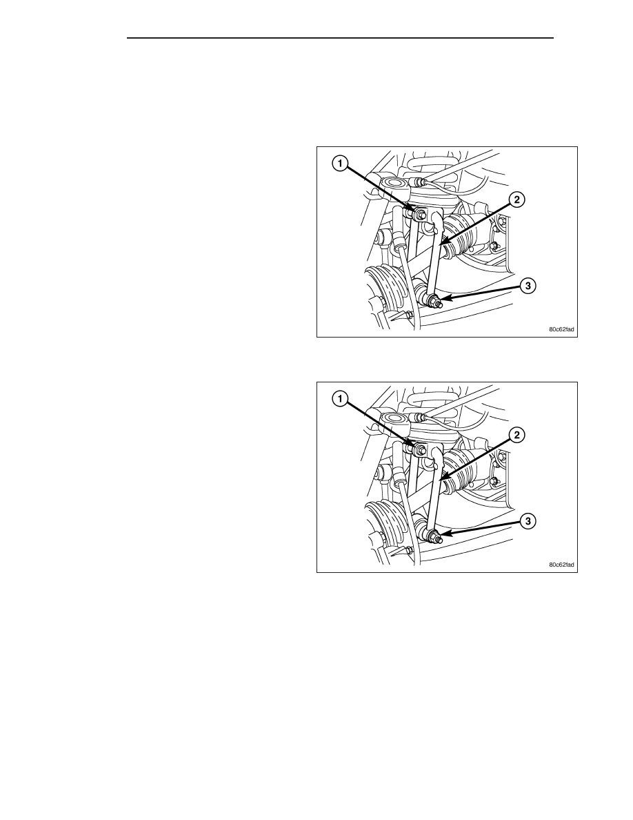
CLEVIS BRACKET
REMOVAL
1. Raise and support the vehicle.
2. Remove the tire and wheel assembly.
3. Remove the lower clevis bolt (3) at the lower con-
trol arm.
4. Remove the upper clevis bolt (1) at the shock.
5. Remove the lower stabilizer link bolt at the lower
control arm.
6. Remove the lower ball joint nut.
7. Separate the lower ball joint from the lower control
arm using remover C-4150A.
8. Swing the lower control arm downward to allow
clearance to remove the clevis bracket (2).
9. Remove the clevis bracket (2) from the vehicle.
INSTALLATION
1. Install the clevis bracket (2) upper bolt (1) to the
shock Seat the clevis against the stop on the
shock. Tighten the bolt (1) to 61 N·m (45 ft.lbs.).
2. Raise the lower control arm to the lower ball joint.
3. Install the nut to the lower ball joint. Tighten the nut
to 81 N·m (60 ft.lbs.).
4. Install the clevis bracket (2) lower bolt (3) to the
lower control arm. Tighten the bolt (3) to 150 N·m
(110 ft.lbs.).
5. Install the lower stabilizer link bolt at the lower con-
trol arm. Tighten the bolt to 115 N·m (85 ft.lbs.).
6. Install the tire and wheel assembly. (Refer to 22 -
TIRES/WHEELS/WHEELS - STANDARD PROCE-
DURE).
7. Lower the vehicle.
2 - 26
FRONT
KJ