Jeep Liberty KJ. Manual - part 18


  Index      Jeep     Jeep Liberty KJ - service repair manual 2006 year


Search            


Content   ..  16  17  18  19   ..


Jeep Liberty KJ. Manual - part 18


SHOCK

REMOVAL

LEFT SIDE

1. Disconnect the battery.

2. Remove the battery (Refer to 8 - ELECTRICAL/BATTERY SYSTEM/BATTERY - REMOVAL).

3. Unclip the power center and move it to the side out of the way.

4. Remove the battery tray (Refer to 8 - ELECTRICAL/BATTERY SYSTEM/TRAY - REMOVAL).

5. Disconnect the battery temperature sensor from the battery tray.

6. Remove the four upper shock mounting nuts.

7. Raise and support the vehicle.

8. Remove the left tire and wheel assembly.

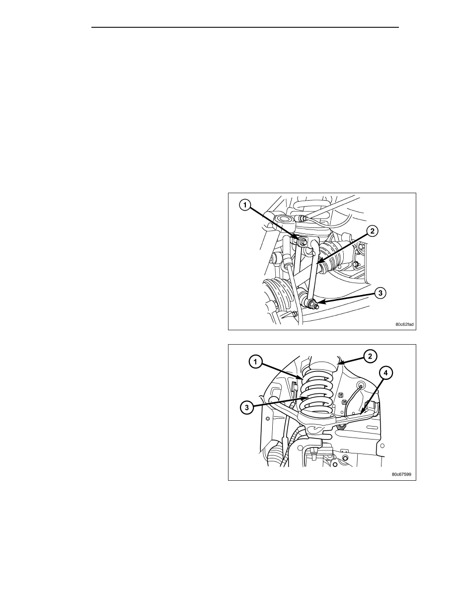
9. Remove the lower bolt (3) at the lower control arm

securing the clevis bracket (2).

10. Remove the stabilizer link (Refer to 2 - SUSPEN-

SION/FRONT/STABILIZER LINK - REMOVAL).

11. Remove the lower ball joint nut.

12. Separate the lower ball joint from the lower con-

trol arm using remover C-4150A.

13. Rotate the lower control arm downward to allow

access.

14. Remove the clevis bracket (2) at the shock.

15. Remove the shock assembly (3) from the vehicle.

16. Remove the spring (1) from the shock (3) (if

needed).

RIGHT SIDE

1. Remove the air box (Refer to 9 - ENGINE/AIR INTAKE SYSTEM/AIR CLEANER ELEMENT - REMOVAL).

2. Remove the two cruise control servo mounting nuts.

3. Remove the upper shock mounting nuts.

4. Raise and support the vehicle.

5. Remove the right side tire assembly.

2 - 22

FRONT

KJ

6. Remove the lower bolt at the lower control arm (5)

securing the clevis bracket (4).

7. Remove the stabilizer link (Refer to 2 - SUSPEN-

SION/FRONT/STABILIZER LINK - REMOVAL).

8. Remove the lower ball joint nut.

9. Separate the lower ball joint from the lower control

arm using remover C-4150A.

10. Rotate the lower control arm downward to allow

access.

11. Remove the clevis bracket (4) at the shock (2).

12. Remove the shock assembly (2) from the vehicle.

13. Remove the spring from the shock (if needed).

(Refer to 2 - SUSPENSION/FRONT/SPRING -
REMOVAL).

INSTALLATION

LEFT SIDE

1. Install the spring (1) to the shock (3) (if removed).

2. Install the shock assembly (3) to the vehicle.

3. Install the four upper shock mounting nuts. Tighten

the nuts to 108 N·m (80 ft.lbs.).

4. Install the clevis bracket (2) at the shock. (Refer to

2 - SUSPENSION/FRONT/CLEVIS BRACKET -
INSTALLATION). Tighten the bolt to 61N·m (45
ft.lbs.).

5. Raise the lower control into place and reconnect

the lower ball joint nut. Tighten the nut to 81 N·m
(60 ft.lbs.).

6. Install the clevis bracket (2) at the lower control

arm. (Refer to 2 - SUSPENSION/FRONT/CLEVIS
BRACKET - INSTALLATION). Tighten the bolt to
150 N·m (110 ft.lbs.).

KJ

FRONT

2 - 23

7. Install the lower stabilizer link at the lower control arm. Tighten the bolt to 136 N·m (100 ft.lbs.) (Refer to 2 -

SUSPENSION/FRONT/STABILIZER LINK - INSTALLATION).

8. Install the left tire and wheel assembly. (Refer to 22 - TIRES/WHEELS/WHEELS - STANDARD PROCEDURE).

9. Lower the vehicle.

10. Reconnect the battery temperature sensor.

11. Install the battery tray (Refer to 8 - ELECTRICAL/BATTERY SYSTEM/TRAY - INSTALLATION).

12. Install the battery (Refer to 8 - ELECTRICAL/BATTERY SYSTEM/BATTERY - INSTALLATION).

13. Reconnect the battery cables.

RIGHT SIDE

1. Install the spring to the shock (if removed). (Refer to 2 - SUSPENSION/FRONT/SPRING - INSTALLATION).

2. Install the shock assembly to the vehicle.

3. Install the four upper shock mounting nuts. Tighten the nuts to 108 N·m (80 ft.lbs.).

4. Install the clevis bracket (4) at the shock (2). (Refer

to 2 - SUSPENSION/FRONT/CLEVIS BRACKET -
INSTALLATION). Tighten the bolt to 61 N·m (45
ft.lbs.).

5. Raise the lower control into place and reconnect

the lower ball joint nut. Tighten the nut to 81 N·m
(60 ft.lbs.).

6. Install the clevis bracket (4) at the lower control

arm (5). (Refer to 2 - SUSPENSION/FRONT/CLE-
VIS BRACKET - INSTALLATION). Tighten the bolt
to 150 N·m (110 ft.lbs.).

7. Install the lower stabilizer link at the lower control

arm. Tighten the bolt to 136 N·m (100 ft.lbs.) (Refer
to 2 - SUSPENSION/FRONT/STABILIZER LINK -
INSTALLATION).

8. Install the right tire and wheel assembly. (Refer to

22

-

TIRES/WHEELS/WHEELS

-

STANDARD

PROCEDURE).

9. Lower the vehicle.

10. Install the cruise control servo mounting nuts.

11. Install the airbox (Refer to 9 - ENGINE/AIR INTAKE SYSTEM/AIR CLEANER ELEMENT - INSTALLATION).

2 - 24

FRONT

KJ

SPRING

REMOVAL

1. Raise and support the vehicle.

2. Remove the tire and wheel assembly.

3. Remove the shock. Refer to the proper side shock removal procedure being worked on. (Refer to 2 - SUSPEN-

SION/FRONT/SHOCK - REMOVAL).

4. Secure the shock assembly into a Pentastar

T

Ser-

vice Equipment W-7200 Spring compressor (1).

5. Compress the spring (2).

6. Remove the shock mount nut.

7. Remove the shock from the spring compressor.

8. Transfer the necessary parts to the type of repair

being done (Insulator, Spring, shock and mount).

INSTALLATION

1. Install the shock to the spring (2) and spring com-

pressor (1), After the transfer of the necessary
parts to the type of repair being done (Insulator,
Spring, shock and mount).

2. Install the shock mounting nut. Tighten the bolt to

41 N·m (30 ft.lbs.).

3. Loosen the compressed spring (2).

4. Remove the shock assembly from the spring com-

pressor (1).

5. Install the shock to the vehicle. (Refer to 2 - SUS-

PENSION/FRONT/SHOCK - INSTALLATION).

6. Install the tire and wheel assembly. (Refer to 22 -

TIRES/WHEELS/WHEELS - STANDARD PROCE-
DURE).

7. Remove the support and lower the vehicle.

KJ

FRONT

2 - 25


Content   ..  16  17  18  19   ..