Jeep Grand Cherokee WK. Manual - part 706


  Index      Jeep     Jeep Grand Cherokee WK - service repair manual 2005 year


Search            


Content   ..  704  705  706  707   ..


Jeep Grand Cherokee WK. Manual - part 706


OPERATION

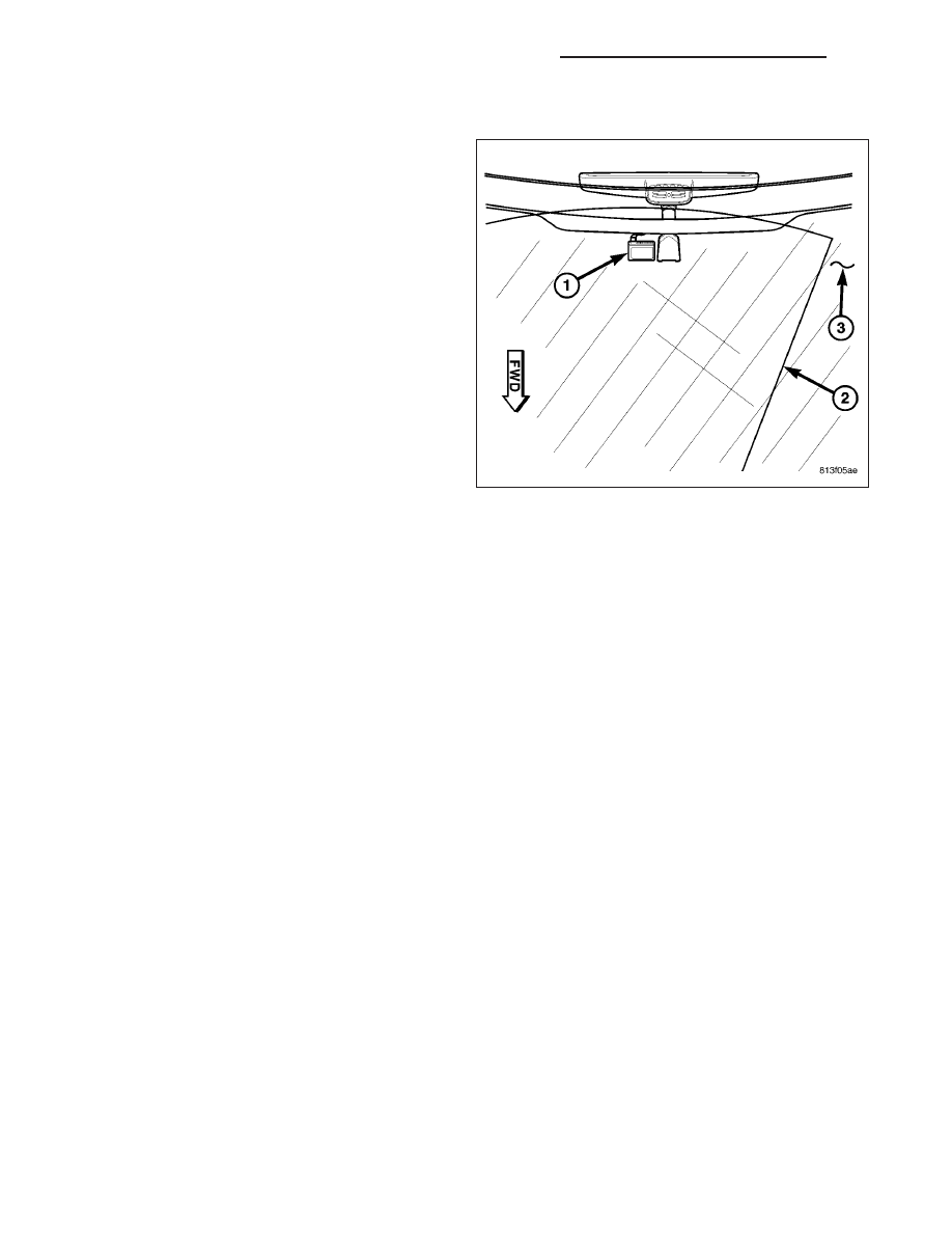
The microprocessor-based rain sensor module (1)
senses moisture in the wipe pattern (2) on the outside
of the windshield glass (3) and sends wipe commands
to the front control module (FCM). Four infrared
diodes within the sensor generate infrared light beams
that are aimed by four of the convex optical lenses
near the base of the sensor through the windshield
glass. Four additional convex optical lenses near the
top of the sensor are focused on the infrared light
beams on the outside of the windshield glass and
allow the four photocells within the sensor to sense
changes in the intensity of these infrared light beams.
When sufficient moisture accumulates within the wipe
pattern on the windshield glass, the sensor detects a
change in the monitored infrared light beam intensity.

The internal programming of the sensor then sends the appropriate electronic wipe command messages to the FCM
over the controller area network (CAN) data bus. The FCM responds by activating or deactivating the front wiper
system. The steering control module (SCM) sends electronic sensitivity level messages to the rain sensor module
over the CAN data bus based upon the driver-selected sensitivity setting of the control knob on the control stalk of
the right multi-function switch. The higher the selected sensitivity setting the more sensitive the rain sensor is to the
accumulated moisture on the windshield glass, and the more frequently the sensor will send wipe commands to the
FCM to operate the front wiper system.

The rain sensor module operates on battery current received through a fuse in the power distribution center (PDC)
on a fused B+ circuit. The rain sensor module receives ground at all times through the body wire harness. It is
important to note that the default condition of the automatic wiper system is low. Therefore, if no message is
received by the FCM from the rain sensor module for more than about five seconds when in the Auto sensitivity
wipe mode, the wipers will default to a constant low wipe state.

The rain sensor module ground and battery current inputs may be diagnosed using conventional diagnostic tools
and methods. The most reliable, efficient, and accurate means to diagnose the rain sensor module requires the use
of a scan tool and the appropriate diagnostic information.

8R - 46

FRONT WIPERS/WASHERS - SERVICE INFORMATION

WK

REMOVAL

1. Disconnect and isolate the negative battery cable.

2. Disconnect the wire harness connector from the

rain sensor module.

3. Using a small screwdriver or equivalent, push in on

the tabs from the connector side of the sensor
housing until the two sliders (1) protrude from the
opposing side of the housing.

4. Gently pull each slider out from the sensor housing

until the cam locks release the sensor from the
mounting bracket located on the windshield glass.

INSTALLATION

1. Verify that the two sliders (1) are positioned in the

downward position, sticking out of the side opposite
of the rain sensor module connector.

2. Position the rain sensor module over the mounting

bracket located on the windshield glass and gently
push down to seat it on the bracket.

3. Push the two sliders inward until they are flush with

the side of the sensor housing and the cam locks
are fully engaged.

4. Connect the wire harness connector to the rain

sensor module.

5. Reconnect the negative battery cable.

WK

FRONT WIPERS/WASHERS - SERVICE INFORMATION

8R - 47

RIGHT MULTI-FUNCTION SWITCH

DESCRIPTION

The right (wiper) multi-function switch (1) is secured to
the right side of the multi-function switch mounting
housing at the top of the steering column, just below
the steering wheel. The only visible component of the
right multi-function switch is the control stalk (2) that
extends through a dedicated opening in the right side
of the steering column shrouds. The remainder of the
right multi-function switch is concealed beneath the
steering column shrouds. The switch housing and its
control stalk are constructed of molded plastic. A sin-
gle connector receptacle is located on the back of the
switch housing and connects the switch directly to the
steering control module (SCM) in the steering column.
The right (wiper) multi-function switch is secured to
the multi-function switch mounting housing near the
top of the steering column by two screws and two
plastic retaining tabs.

The right (wiper) multi-function switch control stalk has
both white nomenclature and International Control and
Display Symbol icons applied to it, which clearly identify its many functions. The control stalk has a control knob (3)
on its end for the front wiper system with a flattened face to allow it to be easily rotated. Just below the control knob
is a knurled control sleeve (4) for the rear wiper/washer system. The right multi-function switch is the primary control
for the front and rear wiper and washer systems, and contains switches and circuitry to provide signals to the SCM.

The right (wiper) multi-function switch cannot be adjusted or repaired and if any function of the switch is faulty, or if
the switch is damaged, the entire right (wiper) multi-function switch must be replaced.

The right (wiper) multi-function switch supports the following functions and features:

Automatic Front Wipe Mode - On models equipped with the optional automatic wiper system, the internal
circuitry and hardware of the right (wiper) multi-function switch control knob provide an automatic front wipe
mode with five sensitivity positions.

Continuous Front Wipe Modes - The internal circuitry and hardware of the right (wiper) multi-function switch
control knob provide two continuous front wipe switch positions, low speed or high speed.

Intermittent Front Wipe Mode - The internal circuitry and hardware of the right (wiper) multi-function switch
control knob provide an intermittent front wipe mode with five delay interval positions, except on models
equipped with the optional automatic wiper system.

Front Wiper Mist Mode - The internal circuitry and hardware of the right (wiper) multi-function switch control
knob provide a front wiper system mist mode.

Front Washer Mode - The internal circuitry and hardware of the right (wiper) multi-function switch control stalk
provide front washer system operation.

Front Wipe-After-Wash Mode - The internal circuitry and hardware of the right (wiper) multi-function switch
control stalk provide a wipe-after-wash mode.

Continuous Rear Wipe Mode - The internal circuitry and hardware of the right (wiper) multi-function switch
control sleeve provides one continuous rear wipe switch position.

Intermittent Rear Wipe Mode - The internal circuitry and hardware of the right (wiper) multi-function switch
control sleeve provide one fixed interval intermittent rear wipe mode switch position.

Rear Washer Mode - The internal circuitry and hardware of the right (wiper) multi-function switch control
sleeve provides two positions for rear washer system operation.

OPERATION

The right (wiper) multi-function switch uses resistor multiplexing to control the many functions and features it pro-
vides. The switch receives a clean ground from the steering control module (SCM) on a multi-function switch return

8R - 48

FRONT WIPERS/WASHERS - SERVICE INFORMATION

WK

circuit. It then provides outputs to the SCM on a wash select switch signal circuit to control washer selection and on
an intermittent wiper switch signal circuit to control the wipers.

The right (wiper) multi-function switch operates as follows:

Washer Control - The control stalk of the right multi-function switch is pulled rearward towards the steering
wheel to momentarily activate the windshield washer pump in the front washer mode. The windshield washer
pump will continue to operate in the front washer mode until the control stalk is released. The windshield
washer pump will operate in the rear washer mode when the knurled control sleeve on the control stalk of the
right multi-function switch is rotated to either of the two rear washer mode positions. The multi-function switch
provides an output to the SCM, which responds by sending electronic washer switch status messages to the
front control module (FCM) over the controller area network (CAN) data bus. The FCM responds by energizing
or de-energizing the windshield washer pump in the front or rear washer mode.

Wiper Control - The control knob on the end of the multi-function switch control stalk is rotated to one of the
two continuous wiper detents, to one of five intermittent wiper detents, or to the Off position to select the front
wiper mode. The rear wiper will operate when the knurled control sleeve on the control stalk of the right multi-
function switch is rotated to either the continuous rear wipe position or to the fixed interval intermittent rear
wipe position. The multi-function switch provides an output to the SCM, which responds by sending electronic
wiper switch status messages to the FCM over the CAN data bus. The FCM responds by energizing or de-
energizing the wiper on/off and high/low relays in the integrated power module (IPM) for wiper system control.

The multi-function switch and the multiplexed inputs to the SCM are diagnosed using a diagnostic scan tool (Refer
to 8R - WIPER/WASHERS - Electrical Diagnostics for more information).

REMOVAL

WARNING: on vehicles equipped with airbags, disable the supplemental restraint system before attempting
any steering wheel, steering column, driver airbag, passenger airbag, seat belt tensioner, side curtain air-
bag, front impact sensor, side impact sensor, or instrument panel component diagnosis or service. discon-
nect and isolate the battery negative (ground) cable, then wait two minutes for the system capacitor to
discharge before performing further diagnosis or service. this is the only sure way to disable the supple-
mental restraint system. failure to take the proper precautions could result in accidental airbag deployment,
possible personal injury or death.

1. Disconnect and isolate the negative battery cable.

2. From below the steering column, remove the three

screws (1) that secure the lower steering column
shroud (2) to the multi-function switch mounting
housing.

3. Using hand pressure, push gently inward on both

sides of the upper shroud (3) near the parting line
between the upper and lower shrouds to release
the snap features that secure the two shroud
halves together.

4. Remove both the upper and lower shrouds from

the steering column.

WK

FRONT WIPERS/WASHERS - SERVICE INFORMATION

8R - 49


Content   ..  704  705  706  707   ..