Content .. 1709 1710 1711 1712 ..
Jeep Grand Cherokee WK. Manual - part 1711
81–BLOWER NOT ON HIGH AT START OF COOLDOWN TEST (MTC) (CONTINUED)
For the Manual Temperature Control (MTC) circuit diagram (Refer to 24 - HEATING & AIR CONDITIONING - SCHE-
MATICS AND DIAGRAMS).
For a complete wiring diagram Refer to Section 8W.
•
When Monitored:
When executing the Cooldown Test.
•
Set Condition:
If the A/C Heater Control sensed that the blower was not operating at high speed when executing the
Cooldown Test.
Possible Causes
BLOWER CONTROL NOT SET TO HIGH SPEED WHEN EXECUTING THE COOLDOWN TEST
BLOWER MOTOR / RELATED CIRCUITS
(C41) BLOWER SWITCH POSITION SIGNAL CIRCUIT SHORTED TO (C121) SENSOR GROUND CIRCUIT
(C41) BLOWER SWITCH POSITION SIGNAL CIRCUIT SHORTED TO GROUND
(C41) BLOWER SWITCH POSITION SIGNAL CIRCUIT OPEN
A/C HEATER CONTROL
NOTE: This DTC will display as active if the ignition is not cycled after running the Cooldown Test. Other-
wise, it will display as stored until cleared.
Diagnostic Test
1.
CHECK THE BLOWER SPEED SETTING
Was the blower control set to high speed before executing the Cooldown Test?
Yes
>> Go To 2
No
>> Start the engine, set the blower control to high speed, and then run the Cooldown Test again.
Perform BODY VERIFICATION TEST - VER 1. (Refer to 8 - ELECTRICAL/ELECTRONIC CONTROL
MODULES - STANDARD PROCEDURE).
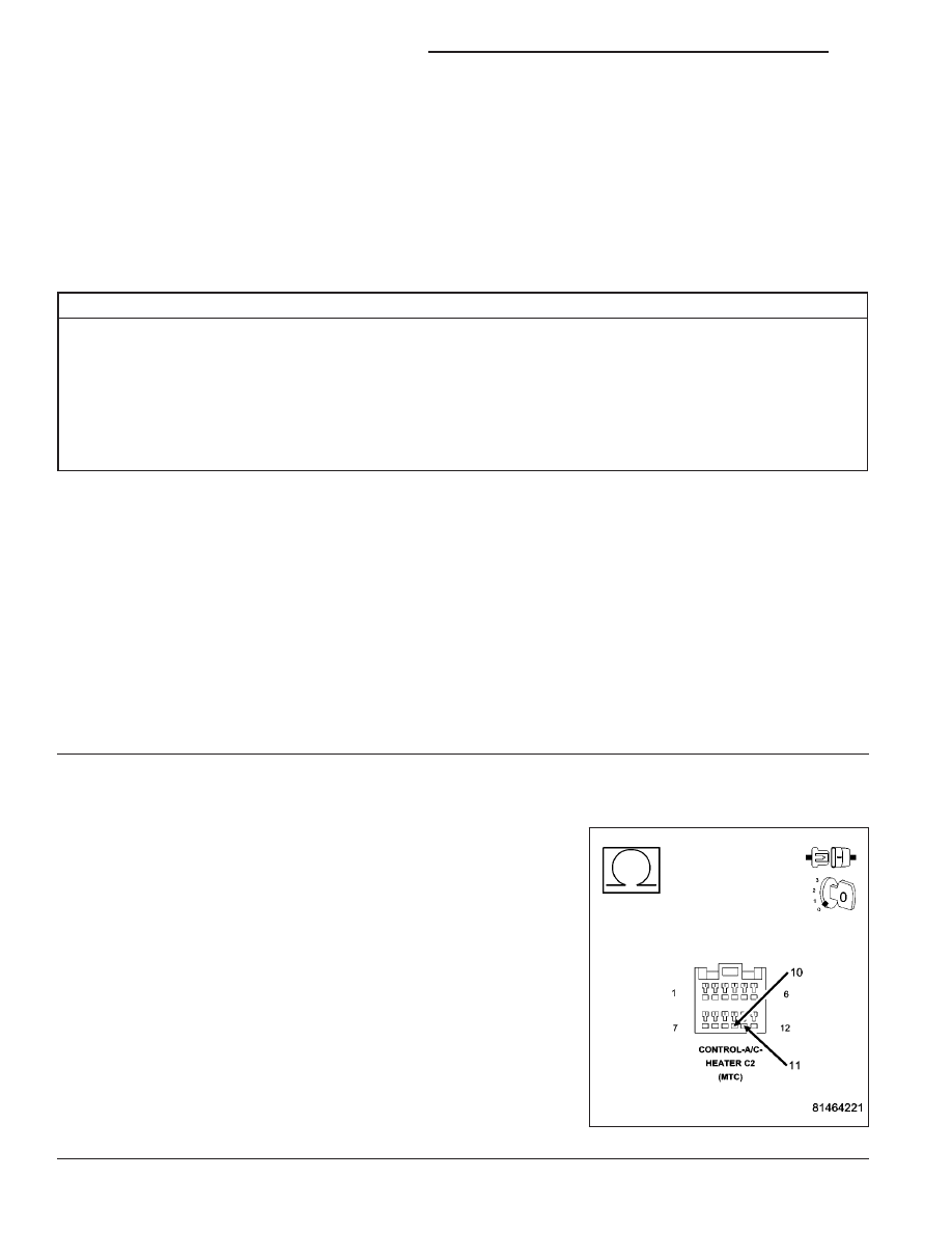
2.
CHECK THE (C41) BLOWER SWITCH POSITION SIGNAL CIRCUIT FOR A SHORT TO THE (C121)
SENSOR GROUND CIRCUIT
Turn the ignition off.
Disconnect the A/C Heater Control C2 harness connector.
Measure the resistance between the (C41) Blower Switch Position Sig-
nal circuit and the (C121) Sensor Ground circuit in the A/C Heater
Control C2 harness connector.
Is the resistance below 10K ohms?
Yes
>> Repair the (C41) Blower Switch Position Signal circuit for
a short to the (C121) Sensor Ground circuit. Run the
Cooldown Test again after the repair is complete.
Perform BODY VERIFICATION TEST - VER 1. (Refer to 8
- ELECTRICAL/ELECTRONIC CONTROL MODULES -
STANDARD PROCEDURE).
No
>> Go To 3
24 - 192
HVAC - ELECTRICAL DIAGNOSTICS
WK