Content .. 1537 1538 1539 1540 ..
Jeep Grand Cherokee WK. Manual - part 1539
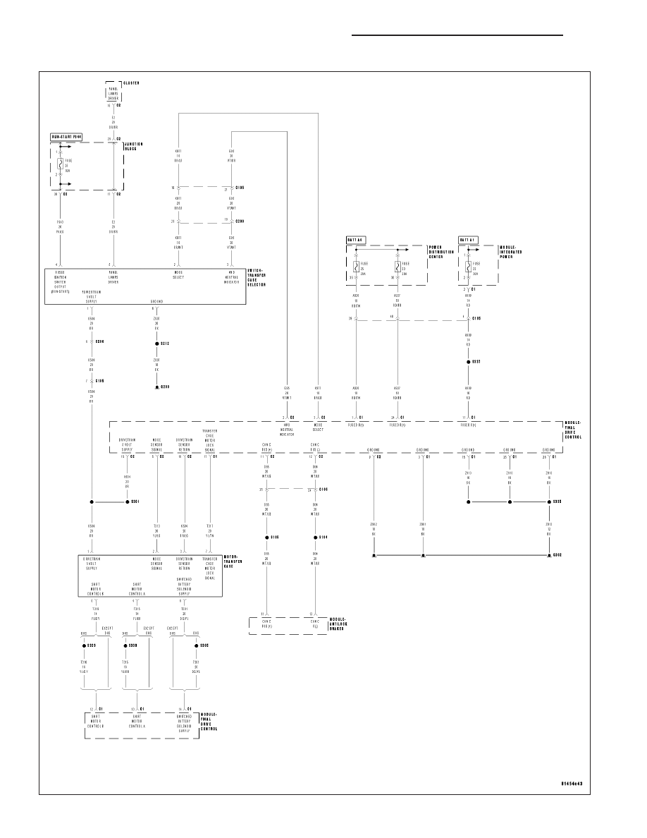
C2111–DRIVETRAIN SENSOR SUPPLY CIRCUIT LOW (FDCM)
21 - 966
TRANSFER CASE - ELECTRICAL DIAGNOSTICS
WK
|
|
|
Content .. 1537 1538 1539 1540 ..
C2111–DRIVETRAIN SENSOR SUPPLY CIRCUIT LOW (FDCM) 21 - 966 TRANSFER CASE - ELECTRICAL DIAGNOSTICS WK |