Jeep Grand Cherokee WK. Manual - part 57
RING GEAR BACKLASH MEASUREMENT
1. Set up Dial Indicator Set C-3339-A with Clamp
SP-5426 (1), Post SP-5425-B (2) and Metric Dial
Indicator 9524 (3) to measure ring gear backlash:
2. Rotate ring gear one direction to take up clearance
to pinion. Verify indicator tip is in contact with ring
gear and zero indicator. Rotate ring gear back and
forth and record measurement. Ring gear backlash
should be 0.13-0.18 mm (0.005-0.007 in.). Verify
back lash measurement in four (4) positions.
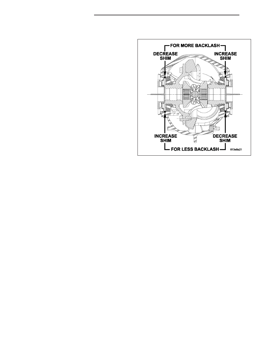
3. If backlash measurement is less than 0.13 mm
(0.005 in.), it is necessary to decrease the snap
ring thickness on the ring gear side, and increase
the thickness on the pinion side equal amounts.
4. If backlash measurement is greater than 0.18 mm
(0.007 in.), it is necessary to increase the snap ring
thickness on the ring gear side, and decrease the
thickness on the pinion side equal amounts.
GEAR CONTACT PATTERN
The ring gear and pinion teeth contact patterns will show if the pinion depth is correct in the housing. It will also
show if the ring gear backlash has been adjusted correctly. The backlash can be adjusted within specifications to
achieve desired tooth contact patterns.
1. Apply a thin coat of hydrated ferric oxide or equivalent to the drive and coast side of the ring gear teeth.
2. Wrap, twist, and hold a shop towel around the pinion yoke to increase the turning resistance of the pinion. This
will provide a more distinct contact pattern.
3. With a boxed end wrench on a ring gear bolt, rotate the differential case one complete revolution in both direc-
tions while a load is being applied from shop towel.
The areas on the ring gear teeth with the greatest degree of contact against the pinion teeth will squeegee the
compound to the areas with the least amount of contact. Note and compare patterns on the ring gear teeth to Gear
Tooth Contact Patterns chart and adjust pinion depth and gear backlash as necessary.
3 - 126
FRONT AXLE - C200FE
WK