Jeep Grand Cherokee WJ. Manual - part 722


  Index      Jeep     Jeep Grand Cherokee WJ - service repair manual 2001 year


Search            


Content   ..  720  721  722  723   ..


Jeep Grand Cherokee WJ. Manual - part 722


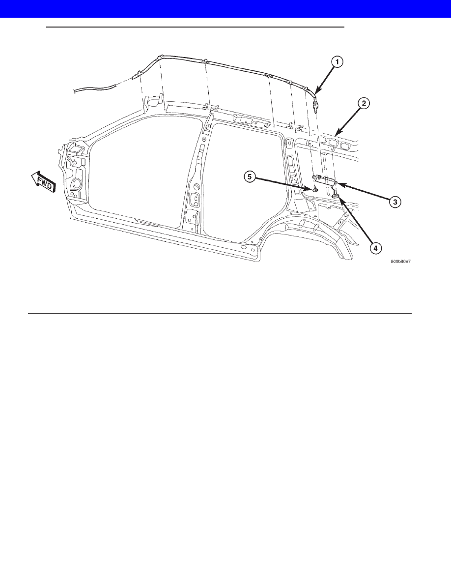
Fig. 2 ANTENNA MODULE

1 - COAX
2 - RIGHT SIDE ROOF RAIL
3 - ANTENNA MODULE

4 - ANTENNA MODULE TO ANTENNA CONNECTOR
5 - SCREW (2)

WG

AUDIO

8As - 3

ANTENNA MODULE (Continued)

2001 JEEP GRAND CHEROKEE

2001 JEEP GRAND CHEROKEE

INSTRUMENT CLUSTER

TABLE OF CONTENTS

page

page

INSTRUMENT CLUSTER

DESCRIPTION . . . . . . . . . . . . . . . . . . . . . . . . . . . . 2
OPERATION . . . . . . . . . . . . . . . . . . . . . . . . . . . . . 3
DIAGNOSIS AND TESTING . . . . . . . . . . . . . . . . . . 5

INSTRUMENT CLUSTER . . . . . . . . . . . . . . . . . . 5

ABS INDICATOR

DESCRIPTION . . . . . . . . . . . . . . . . . . . . . . . . . . . . 8
OPERATION . . . . . . . . . . . . . . . . . . . . . . . . . . . . . 8

AIRBAG INDICATOR

DESCRIPTION . . . . . . . . . . . . . . . . . . . . . . . . . . . . 8
OPERATION . . . . . . . . . . . . . . . . . . . . . . . . . . . . . 8

BRAKE/PARK BRAKE INDICATOR

DESCRIPTION . . . . . . . . . . . . . . . . . . . . . . . . . . . . 9
OPERATION . . . . . . . . . . . . . . . . . . . . . . . . . . . . . 9
DIAGNOSIS AND TESTING . . . . . . . . . . . . . . . . . 10

BRAKE INDICATOR . . . . . . . . . . . . . . . . . . . . . 10

CHECK GAUGES INDICATOR

DESCRIPTION . . . . . . . . . . . . . . . . . . . . . . . . . . . 11
OPERATION. . . . . . . . . . . . . . . . . . . . . . . . . . . . . 11

CRUISE INDICATOR

DESCRIPTION . . . . . . . . . . . . . . . . . . . . . . . . . . . 12
OPERATION. . . . . . . . . . . . . . . . . . . . . . . . . . . . . 12

ENGINE TEMPERATURE GAUGE

DESCRIPTION . . . . . . . . . . . . . . . . . . . . . . . . . . . 13
OPERATION. . . . . . . . . . . . . . . . . . . . . . . . . . . . . 13

FRONT FOG LAMPS INDICATOR

DESCRIPTION . . . . . . . . . . . . . . . . . . . . . . . . . . . 14
OPERATION. . . . . . . . . . . . . . . . . . . . . . . . . . . . . 14

FUEL GAUGE

DESCRIPTION . . . . . . . . . . . . . . . . . . . . . . . . . . . 14
OPERATION. . . . . . . . . . . . . . . . . . . . . . . . . . . . . 14

HIGH BEAM INDICATOR

DESCRIPTION . . . . . . . . . . . . . . . . . . . . . . . . . . . 15
OPERATION. . . . . . . . . . . . . . . . . . . . . . . . . . . . . 15

LOW COOLANT INDICATOR

DESCRIPTION . . . . . . . . . . . . . . . . . . . . . . . . . . . 16
OPERATION. . . . . . . . . . . . . . . . . . . . . . . . . . . . . 16

LOW FUEL INDICATOR

DESCRIPTION . . . . . . . . . . . . . . . . . . . . . . . . . . . 16
OPERATION. . . . . . . . . . . . . . . . . . . . . . . . . . . . . 17

MALFUNCTION INDICATOR LAMP (MIL)

DESCRIPTION . . . . . . . . . . . . . . . . . . . . . . . . . . . 17
OPERATION. . . . . . . . . . . . . . . . . . . . . . . . . . . . . 17

ODOMETER

DESCRIPTION . . . . . . . . . . . . . . . . . . . . . . . . . . . 18
OPERATION. . . . . . . . . . . . . . . . . . . . . . . . . . . . . 18

OIL PRESSURE GAUGE

DESCRIPTION . . . . . . . . . . . . . . . . . . . . . . . . . . . 19
OPERATION. . . . . . . . . . . . . . . . . . . . . . . . . . . . . 19

REAR FOG LAMPS INDICATOR

DESCRIPTION . . . . . . . . . . . . . . . . . . . . . . . . . . . 20
OPERATION. . . . . . . . . . . . . . . . . . . . . . . . . . . . . 20

OVERDRIVE OFF INDICATOR

DESCRIPTION . . . . . . . . . . . . . . . . . . . . . . . . . . . 20
OPERATION. . . . . . . . . . . . . . . . . . . . . . . . . . . . . 21

SEATBELT INDICATOR

DESCRIPTION . . . . . . . . . . . . . . . . . . . . . . . . . . . 21
OPERATION. . . . . . . . . . . . . . . . . . . . . . . . . . . . . 21

SHIFT INDICATOR (TRANSFER CASE)

DESCRIPTION . . . . . . . . . . . . . . . . . . . . . . . . . . . 22
OPERATION. . . . . . . . . . . . . . . . . . . . . . . . . . . . . 22
DIAGNOSIS AND TESTING . . . . . . . . . . . . . . . . . 22

PART TIME INDICATOR . . . . . . . . . . . . . . . . . . 22

SPEEDOMETER

DESCRIPTION . . . . . . . . . . . . . . . . . . . . . . . . . . . 23
OPERATION. . . . . . . . . . . . . . . . . . . . . . . . . . . . . 24

TACHOMETER

DESCRIPTION . . . . . . . . . . . . . . . . . . . . . . . . . . . 24
OPERATION. . . . . . . . . . . . . . . . . . . . . . . . . . . . . 24

TRANS OVERTEMP INDICATOR

DESCRIPTION . . . . . . . . . . . . . . . . . . . . . . . . . . . 25
OPERATION. . . . . . . . . . . . . . . . . . . . . . . . . . . . . 25

TURN SIGNAL INDICATORS

DESCRIPTION . . . . . . . . . . . . . . . . . . . . . . . . . . . 26
OPERATION. . . . . . . . . . . . . . . . . . . . . . . . . . . . . 26
DIAGNOSIS AND TESTING . . . . . . . . . . . . . . . . . 26

TURN SIGNAL INDICATORS . . . . . . . . . . . . . . 26

VOLTAGE GAUGE

DESCRIPTION . . . . . . . . . . . . . . . . . . . . . . . . . . . 27
OPERATION. . . . . . . . . . . . . . . . . . . . . . . . . . . . . 27

WAIT-TO-START INDICATOR

DESCRIPTION . . . . . . . . . . . . . . . . . . . . . . . . . . . 27
OPERATION. . . . . . . . . . . . . . . . . . . . . . . . . . . . . 28

WATER-IN-FUEL INDICATOR

DESCRIPTION . . . . . . . . . . . . . . . . . . . . . . . . . . . 28
OPERATION. . . . . . . . . . . . . . . . . . . . . . . . . . . . . 28

WG

INSTRUMENT CLUSTER

8Js - 1

2001 JEEP GRAND CHEROKEE

INSTRUMENT CLUSTER

DESCRIPTION

This Service Manual Supplement includes

ONLY the information that is new or updated
for 2001 Model Year. All other Service Manual
information is in the 2000 Model Year Service
Manual.

When you are using this information you may

be referred to another section of the Service
Manual. The refer to is written differently than
in prior years.

DESCRIPTION

The instrument cluster for this model is an Elec-

troMechanical Instrument Cluster (EMIC) module
that is located in the instrument panel above the
steering column opening, directly in front of the
driver (Fig. 1). The remainder of the EMIC, including
the mounts and the electrical connections, are con-
cealed at the back of the cluster housing or behind
the cluster bezel. The molded plastic EMIC housing
has four integral mounting tabs, two on the lower
edge of the housing and two on the upper edge. The
EMIC is secured to the molded plastic instrument
panel cluster carrier with two screws, and to the
underside of the instrument panel top pad hood for-
mation with two screws. All electrical connections to
the EMIC are made at the back of the cluster hous-
ing through a single take out and connector of the
instrument panel wire harness.

The EMIC gauges and indicators are protected by

an integral clear plastic cluster lens, and are visible
through a dedicated hooded opening in the instru-

ment panel top pad. Just behind the cluster lens is
the cluster hood and mask. The cluster hood serves
as a visor and shields the face of the cluster from
ambient light and reflections to reduce glare. The
cluster mask and the dial faces of the gauges are
multi-layered units. The mask features two large
round openings near its center through which the
two major gauges are visible, and two smaller round
openings stacked at the outboard side of each of the
large openings through which the four minor gauges
are visible. The dark, visible surface of the mask and
the gauge dial faces are the outer layer or overlay,
which is translucent. The darkness of this outer layer
prevents the cluster from appearing too cluttered or
busy by concealing the cluster indicators that are not
illuminated, while the translucence of this layer
allows those indicators and icons that are illumi-
nated to be readily visible. The underlying layer of
the overlay is opaque and allows light from the var-
ious indicator lamps behind it to be visible through
the outer layer of the mask and gauge dial faces only
through predetermined cutouts. The graphics, incre-
ments, and numerals on the gauge faces are also
translucent and illuminated from behind, while the
orange gauge pointers are illuminated internally. On
the lower edge of the cluster lens just right of center,
a small molded plastic odometer/trip odometer switch
knob protrudes through a dedicated hole in the lens.

Two EMIC modules are offered on this model, one

for Laredo models featuring black gauge dial faces,
and one for Limited models with gauge dial faces
that feature a brushed aluminum appearance. This
module utilizes integrated circuitry and information
carried on the Programmable Communications Inter-
face (PCI) data bus network for control of all gauges
and many of the indicator lamps. (Refer to 8 - ELEC-
TRICAL/ELECTRONIC

CONTROL

MODULES/

COMMUNICATION - DESCRIPTION). The EMIC
also uses several hard wired inputs in order to per-
form its many functions. The EMIC module incorpo-
rates

a

blue-green

electronic

digital

VFD

for

displaying odometer and trip odometer information,
as well as the cruise-on indicator display function.
Some variations of this cluster exist due to optional
equipment and regulatory requirements. The EMIC
includes the following analog gauges:

• Coolant Temperature Gauge

• Fuel Gauge

• Oil Pressure Gauge

• Speedometer

• Tachometer

• Voltage Gauge
This EMIC also includes provisions for the follow-

ing indicator lamps:

• Airbag Indicator

• Antilock Brake System (ABS) Indicator

Fig. 1 Instrument Cluster

1 - INSTRUMENT PANEL TOP PAD HOOD FORMATION
2 - INSTRUMENT CLUSTER
3 - CLUSTER BEZEL

8Js - 2

INSTRUMENT CLUSTER

WG

2001 JEEP GRAND CHEROKEE


Content   ..  720  721  722  723   ..