Jeep Grand Cherokee WJ. Manual - part 720


  Index      Jeep     Jeep Grand Cherokee WJ - service repair manual 2001 year


Search            


Content   ..  718  719  720  721   ..


Jeep Grand Cherokee WJ. Manual - part 720


RADIATOR

DESCRIPTION

All vehicles are equipped with a cross flow type

radiator with plastic side tanks (Fig. 7).

Plastic tanks, while stronger than brass, are sub-

ject to damage by impact, such as from tools or
wrenches. Handle radiator with care.

REMOVAL

WARNING:

DO

NOT

REMOVE

THE

CYLINDER

BLOCK DRAIN PLUGS OR LOOSEN THE RADIATOR
DRAINCOCK WITH THE SYSTEM HOT AND UNDER
PRESSURE. SERIOUS BURNS FROM COOLANT
CAN OCCUR. REFER TO COOLING SYSTEM DRAIN-
ING.

Do not waste reusable coolant. If the solution is

clean, drain the coolant into a clean container for
reuse.

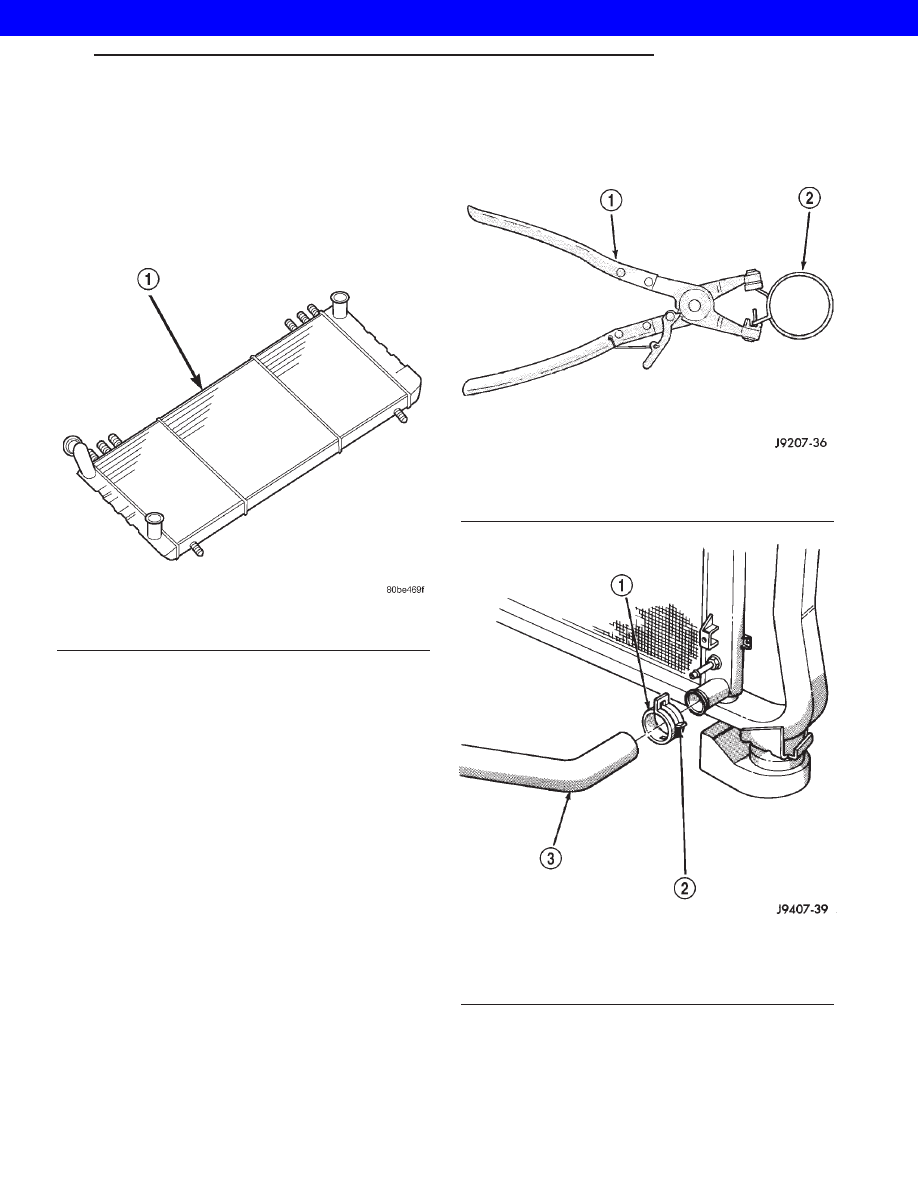
WARNING: CONSTANT TENSION HOSE CLAMPS
ARE USED ON MOST COOLING SYSTEM HOSES.
WHEN REMOVING OR INSTALLING, USE ONLY
TOOLS DESIGNED FOR SERVICING THIS TYPE OF
CLAMP, SUCH AS SPECIAL CLAMP TOOL (NUMBER
6094) (Fig. 8). SNAP-ON CLAMP TOOL (NUMBER
HPC-20) MAY BE USED FOR LARGER CLAMPS.
ALWAYS WEAR SAFETY GLASSES WHEN SERVIC-
ING CONSTANT TENSION CLAMPS.

CAUTION: A number or letter is stamped into the
tongue of constant tension clamps (Fig. 9). If
replacement is necessary, use only an original
equipment clamp with matching number or letter.

Fig. 7 Cross Flow Radiator—Typical

1 - RADIATOR

Fig. 8 Hose Clamp Tool—Typical

1 - HOSE CLAMP TOOL 6094
2 - HOSE CLAMP

Fig. 9 Clamp Number/Letter Location—Typical

1 - TYPICAL CONSTANT TENSION HOSE CLAMP
2 - CLAMP NUMBER/LETTER LOCATION
3 - TYPICAL HOSE

WG

ENGINE 4.7L

7s - 25

2001 JEEP GRAND CHEROKEE

CAUTION: When removing the radiator or A/C con-
denser for any reason, note the location of all radi-
ator-to-body and radiator-to-A/C condenser rubber
air seals (Fig. 10). These are used at the top, bot-
tom and sides of the radiator and A/C condenser.
To

prevent

overheating,

these

seals

must

be

installed to their original positions.

(1) Disconnect the negative battery cable at bat-

tery.

(2) Drain coolant from radiator (Refer to 7 -

COOLING - STANDARD PROCEDURE) .

(3) Remove the front grill (Refer to 23 - BODY/EX-

TERIOR/GRILLE - REMOVAL).

(4) Remove two radiator mounting bolts.
(5) Disconnect both transmission cooler lines from

radiator.

(6) Disconnect electrical connector for the fan con-

trol solenoid.

(7) Disconnect the power steering cooler line from

cooler and filter.

(8) Disconnect the radiator upper and lower hoses.
(9) Disconnect the overflow hose from radiator.
(10) Remove the air inlet duct at the grill.
(11) The lower part of radiator is equipped with

two alignment dowel pins (Fig. 11). They are located
on the bottom of radiator tank and fit into rubber
grommets. These rubber grommets are pressed into
the radiator lower crossmember.

WARNING: THE AIR CONDITIONING SYSTEM (IF
EQUIPPED) IS UNDER A CONSTANT PRESSURE
EVEN WITH THE ENGINE OFF. REFER TO REFRIG-
ERANT WARNINGS IN, HEATING AND AIR CONDI-
TIONING

BEFORE

HANDLING

ANY

AIR

CONDITIONING COMPONENT.

NOTE: The radiator and radiator cooling fan can be
removed as an assembly. It is not necessary to
remove the cooling fan before removing or install-
ing the radiator.

(12) Disconnect the two high pressure fluid lines

at the hydraulic fan drive.

(13) Disconnect the low pressure return hose at

the hydraulic fan drive.

(14) Gently lift up and remove radiator from vehi-

cle. Be careful not to scrape the radiator fins against
any other component. Also be careful not to disturb
the air conditioning condenser (if equipped).

CLEANING

Clean radiator fins. With the engine cold, apply

cold water and compressed air to the back (engine
side) of the radiator to flush the radiator and/or A/C
condenser of debris.

Fig. 10 Air Seals—Typical

1 - AIR DAM
2 - RADIATOR
3 - AIR DAM
4 - A/C CONDENSER
5 - AIR SEAL

Fig. 11 Radiator Alignment Dowels

1 - RADIATOR
2 - ALIGNMENT DOWEL
3 - RADIATOR LOWER ISOLATOR
4 - RADIATOR LOWER CROSSMEMBER

7s - 26

ENGINE 4.7L

WG

RADIATOR (Continued)

2001 JEEP GRAND CHEROKEE

INSPECTION

The radiator cooling fins should be checked for

damage or deterioration. Inspect cooling fins to make
sure they are not bent or crushed, these areas result
in reduced heat exchange causing the cooling system
to operate at higher temperatures. Inspect the plastic
end tanks for cracks, damage or leaks.

Inspect the radiator neck for damage or distortion.

INSTALLATION

CAUTION: Before installing the radiator or A/C con-
denser, be sure the radiator-to-body and radiator-to-
A/C condenser rubber air seals (Fig. 6) are properly
fastened to their original positions. These are used
at the top, bottom and sides of the radiator and A/C
condenser. To prevent overheating, these seals
must be installed to their original positions.

(1) Equipped with air conditioning: Gently lower

the radiator and fan shroud into the vehicle. Guide
the two radiator alignment dowels through the holes
in the rubber air seals first and then through the A/C
support brackets (Fig. 7). Continue to guide the
alignment dowels into the rubber grommets located
in lower radiator crossmember. The holes in the
L-shaped brackets (located on bottom of A/C con-
denser) must be positioned between bottom of rubber
air seals and top of rubber grommets.

(2) Connect the radiator upper and lower hoses

and hose clamps to radiator.

CAUTION: The tangs on the hose clamps must be
positioned straight down.

(3) Install coolant reserve/overflow tank hose at

radiator.

(4) Connect both transmission cooler lines at the

radiator.

(5) Install both radiator mounting bolts.
(6) Install air inlet duct at grill.
(7) Attach electric connector for hydraulic fan con-

trol solenoid.

(8) Install the grill (Refer to 23 - BODY/EXTERI-

OR/GRILLE - INSTALLATION).

(9) Connect the two high pressure lines to the

hydraulic fan drive. Tighten ½ in. pressure line fit-
ting to 49 N·m (36 ft. lbs.). and the 3/8 in. pressure
line fitting to 29 N·m (21.5 ft. lbs.).

(10) Connect the low pressure hose to the hydrau-

lic fan drive. Position the spring clamp.

(11) Connect the power steering filter hoses to the

filter. Install new hose clamps.

(12) Rotate the fan blades (by hand) and check for

interference at fan shroud.

(13) Refill cooling system (Refer to 7 - COOLING -

STANDARD PROCEDURE).

(14) Refill the power steering reservoir and bleed

air from system (Refer to 19 - STEERING/PUMP -
STANDARD PROCEDURE).

(15) Connect battery cable at battery.
(16) Start and warm engine. Check for leaks.

WATER PUMP - 4.7L

DESCRIPTION—WATER PUMP

A

centrifugal

water

pump

circulates

coolant

through the water jackets, passages, intake manifold,
radiator core, cooling system hoses and heater core.
The pump is driven from the engine crankshaft by a
single serpentine drive belt.

The water pump impeller is pressed onto the rear

of a shaft that rotates in bearings pressed into the
housing. The housing has two small holes to allow
seepage to escape. The water pump seals are lubri-
cated by the antifreeze in the coolant mixture. No
additional lubrication is necessary.

Both heater hoses are connected to fittings on the

timing chain front cover. The water pump is also
mounted directly to the timing chain cover and is
equipped with a non serviceable integral pulley (Fig.
12).

Fig. 12 Water Pump and Timing Chain Cover

1 - INTEGRAL WATER PUMP PULLEY
2 - TIMING CHAIN COVER
3 - THERMOSTAT HOUSING
4 - HEATER HOSE FITTINGS
5 - WATER PUMP

WG

ENGINE 4.7L

7s - 27

RADIATOR (Continued)

2001 JEEP GRAND CHEROKEE

DESCRIPTION - WATER PUMP BYPASS

The 4.7L engine uses an internal water/coolant

bypass system. The design uses galleries in the tim-
ing chain cover to circulate coolant during engine
warm-up

preventing

the

coolant

from

flowing

through the radiator. The thermostat uses a stub
shaft located at the rear of the thermostat (Fig. 13)
to control flow through the bypass gallery.

OPERATION - WATER PUMP

A

centrifugal

water

pump

circulates

coolant

through the water jackets, passages, intake manifold,
radiator core, cooling system hoses and heater core,
this coolant absorbs the heat generated when the
engine is running. The pump is driven by the engine
crankshaft via a drive belt.

OPERATION - WATER PUMP BYPASS

When the thermostat is in the closed position the

bypass gallery is not obstructed allowing 100% flow.
When the thermostat is in the open position the stub
shaft enters the bypass gallery obstructing bypass

coolant flow by 50%. This design allows the coolant
to reach operating temperature quickly when cold,
while adding extra cooling during normal tempera-
ture operation.

DIAGNOSIS AND TESTING - WATER PUMP

LOOSE IMPELLER

NOTE: Due to the design of the 4.7L engine water
pump, testing the pump for a loose impeller must
be done by verifying coolant flow in the radiator. To
accomplish this refer to the following procedure.

DO NOT WASTE reusable coolant. If solution is

clean, drain coolant into a clean container for reuse.

(1) Drain coolant until the first row of cores is vis-

ible in the radiator (Refer to 7 - COOLING - STAN-
DARD PROCEDURE).

(2) Leaving the radiator cap off, start the engine.

Run engine until thermostat opens.

(3) While looking into the radiator through the

radiator fill neck, raise engine rpm to 2000 RPM.
Observe the flow of coolant from the first row of
cores.

(4) If there is no flow or very little flow visable,

replace the water pump.

INSPECTING FOR INLET RESTRICTIONS

Inadequate heater performance may be caused by

a metal casting restriction in the heater hose inlet.

DO NOT WASTE reusable coolant. If solution is

clean, drain the coolant into a clean container for
reuse.

WARNING:

DO

NOT

LOOSEN

THE

RADIATOR

DRAINCOCK WITH THE SYSTEM HOT AND UNDER
PRESSURE. SERIOUS BURNS FROM THE COOL-
ANT CAN OCCUR.

(1) Drain sufficient coolant from the radiator to

decrease the level below the heater hose inlet. On
4.7L engines this requires complete draining.

(2) Remove the heater hose.
(3) Inspect the inlet for metal casting flash or

other restrictions.

NOTE: On 4.7L engine remove the fitting from the
timing chain cover, If the restriction is in the timing
chain cover, remove the timing chain cover.

Fig. 13 Water/Coolant Bypass Flow and Thermostat

1 - FROM HEATER
2 - FROM RADIATOR
3 - TO WATER PUMP
4 - ENGINE BYPASS
5 - THERMOSTAT

7s - 28

ENGINE 4.7L

WG

WATER PUMP - 4.7L (Continued)

2001 JEEP GRAND CHEROKEE


Content   ..  718  719  720  721   ..