Jeep Grand Cherokee WJ. Manual - part 718


  Index      Jeep     Jeep Grand Cherokee WJ - service repair manual 2001 year


Search            


Content   ..  716  717  718  719   ..


Jeep Grand Cherokee WJ. Manual - part 718


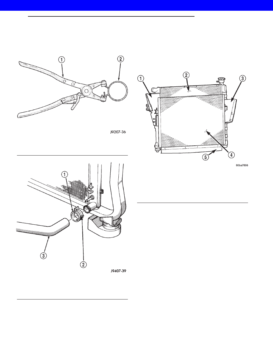
CAUTION: A number or letter is stamped into the
tongue of constant tension clamps (Fig. 5). If
replacement is necessary, use only an original
equipment clamp with matching number or letter.

CAUTION: When removing the radiator or A/C con-
denser for any reason, note the location of all radi-
ator-to-body and radiator-to-A/C condenser rubber
air seals (Fig. 6). These are used at the top, bottom
and sides of the radiator and A/C condenser. To
prevent overheating, these seals must be installed
to their original positions.

(1) Disconnect the negative battery cable at bat-

tery.

(2) Drain coolant from radiator (Refer to 7 -

COOLING - STANDARD PROCEDURE).

(3) Do not attempt to remove fan/viscous fan drive

assembly from vehicle at this time.

(4) Remove the front grill (Refer to 23 - BODY/EX-

TERIOR/GRILLE - REMOVAL).

(5) Remove two radiator mounting bolts (Fig. 8).
(6) Disconnect both transmission cooler lines from

radiator.

(7) Disconnect electric fan connector, then discon-

nect connector harness from shroud (Fig. 8).

(8) Disconnect the radiator upper and lower hoses

(Fig. 8).

(9) Disconnect the overflow hose from radiator

(Fig. 8).

(10) Remove the air inlet duct at the grill.

Fig. 4 Hose Clamp Tool - Typical

1 - HOSE CLAMP TOOL 6094
2 - HOSE CLAMP

Fig. 5 Clamp Number/Letter Location - Typical

1 - TYPICAL CONSTANT TENSION HOSE CLAMP
2 - CLAMP NUMBER/LETTER LOCATION
3 - TYPICAL HOSE

Fig. 6 Air Seals - Typical

1 - AIR DAM
2 - RADIATOR
3 - AIR DAM
4 - A/C CONDENSER
5 - AIR SEAL

WG

ENGINE 4.0L

7s - 17

RADIATOR - 4.0L (Continued)

2001 JEEP GRAND CHEROKEE

(11) The lower part of radiator is equipped with

two alignment dowel pins (Fig. 7). They are located
on the bottom of radiator tank and fit into rubber
grommets. These rubber grommets are pressed into
the radiator lower crossmember.

WARNING: THE AIR CONDITIONING SYSTEM (IF
EQUIPPED) IS UNDER A CONSTANT PRESSURE
EVEN WITH THE ENGINE OFF. REFER TO REFRIG-
ERANT WARNINGS IN GROUP 24, HEATING AND
AIR CONDITIONING BEFORE HANDLING ANY AIR
CONDITIONING COMPONENT.

(12) If equipped with an auxiliary automatic trans-

mission oil cooler, use caution when removing radia-
tor. The oil cooler lines are routed through a rubber
air seal on the right side of radiator. Do not cut or
tear this seal.

(13) Gently lift up and remove radiator from vehi-

cle. Be careful not to scrape the radiator fins against
any other component. Also be careful not to disturb
the air conditioning condenser (if equipped).

CLEANING

Clean radiator fins With the engine cold, apply cold

water and compressed air to the back (engine side) of
the radiator to flush the radiator and/or A/C con-
denser of debris.

INSPECTION

The radiator cooling fins should be checked for

damage or deterioration. Inspect cooling fins to make
sure they are not bent or crushed, these areas result
in reduced heat exchange causing the cooling system
to operate at higher temperatures. Inspect the plastic
end tanks for cracks, damage or leaks.

Inspect the radiator neck for damage or distortion.

INSTALLATION

CAUTION: Before installing the radiator or A/C con-
denser, be sure the radiator-to-body and radiator-to-
A/C condenser rubber air seals (Fig. 6) are properly
fastened to their original positions. These are used
at the top, bottom and sides of the radiator and A/C
condenser. To prevent overheating, these seals
must be installed to their original positions.

(1) Equipped with air conditioning: Gently lower

the radiator into the vehicle. Guide the two radiator
alignment dowels through the holes in the rubber air
seals first and then through the A/C support brackets
(Fig. 7). Continue to guide the alignment dowels into
the rubber grommets located in lower radiator cross-
member. The holes in the L-shaped brackets (located
on bottom of A/C condenser) must be positioned
between bottom of rubber air seals and top of rubber
grommets.

Fig. 7 Radiator Alignment Dowels

1 - RADIATOR
2 - ALIGNMENT DOWEL
3 - RADIATOR LOWER ISOLATOR
4 - RADIATOR LOWER CROSSMEMBER

Fig. 8 Radiator, Shroud and Electric Fan

1 - RADIATOR/SHROUD/FAN ASSEMBLY
2 - OVER FLOW HOSE
3 - ELECTRIC FAN CONNECTOR
4 - RADIATOR MOUNTING BOLT(S)
5 - CLAMP

7s - 18

ENGINE 4.0L

WG

RADIATOR - 4.0L (Continued)

2001 JEEP GRAND CHEROKEE

(2) Connect the radiator upper and lower hoses

and hose clamps to radiator (Fig. 8).

CAUTION: The tangs on the hose clamps must be
positioned straight down.

(3) Install coolant reserve/overflow tank hose at

radiator (Fig. 8).

(4) Connect both transmission cooler lines at the

radiator (Fig. 8).

(5) Install both radiator mounting bolts (Fig. 8).
(6) Install air inlet duct at grill.
(7) Attach electric fan harness to shroud, then con-

nect harness to connector (Fig. 8).

(8) Install the grill (Refer to 23 - BODY/EXTERI-

OR/GRILLE - INSTALLATION).

(9)

Install the fan/viscous fan drive assembly to

the water pump.

(10) Rotate the fan blades (by hand) and check for

interference at fan shroud.

(11) Be sure of at least 25 mm (1.0 inch) between

tips of fan blades and fan shroud.

(12) Fill cooling system (Refer to 7 - COOLING -

STANDARD PROCEDURE).

(13) Connect battery cable at battery.
(14) Start and warm engine. Check for leaks.

COOLANT LEVEL SENSOR

REMOVAL

(1) Open Hood.
(2) Disconnect electrical connector from coolant

level sensor.

(3) Pull coolant level sensor out of coolant recovery

pressure container.

INSTALLATION

NOTE: Make sure the coolant level sensor fully
seats into the rubber grommet. Failure to do so
may cause inaccurate coolant level readings and
leaks.

(1) Position sensor into the coolant recovery pres-

sure container (Fig. 9).

(2) Connect the coolant level sensor electrical con-

nector (Fig. 10).

(3) Close hood.

Fig. 9 COOLANT LEVEL SENSOR ELECTRICAL

CONNECTOR

Fig. 10 COOLANT LEVEL SENSOR REMOVAL/

INSTALLATION

WG

ENGINE 4.0L

7s - 19

RADIATOR - 4.0L (Continued)

2001 JEEP GRAND CHEROKEE

ENGINE COOLANT TEMP
SENSOR

DESCRIPTION

The Engine Coolant Temperature (ECT) sensor is

used to sense engine coolant temperature. The sensor
protrudes into an engine water jacket.

The ECT sensor is a two-wire Negative Thermal

Coefficient (NTC) sensor. Meaning, as engine coolant
temperature increases, resistance (voltage) in the
sensor decreases. As temperature decreases, resis-
tance (voltage) in the sensor increases.

OPERATION

At key-on, the Powertrain Control Module (PCM)

sends out a regulated 5 volt signal to the ECT sensor.
The PCM then monitors the signal as it passes
through the ECT sensor to the sensor ground (sensor
return).

When the engine is cold, the PCM will operate in

Open Loop cycle. It will demand slightly richer air-
fuel mixtures and higher idle speeds. This is done
until normal operating temperatures are reached.

The PCM uses inputs from the ECT sensor for the

following calculations:

• for engine coolant temperature gauge operation

through CCD or PCI (J1850) communications

• Injector pulse-width

• Spark-advance curves

• ASD relay shut-down times

• Idle Air Control (IAC) motor key-on steps

• Pulse-width prime-shot during cranking

• O2 sensor closed loop times

• Purge solenoid on/off times

• EGR solenoid on/off times (if equipped)

• Leak Detection Pump operation (if equipped)

• Radiator fan relay on/off times (if equipped)

• Target idle speed

REMOVAL—4.0L ENGINE

WARNING: HOT, PRESSURIZED COOLANT CAN
CAUSE INJURY BY SCALDING. COOLING SYSTEM
MUST BE PARTIALLY DRAINED BEFORE REMOV-
ING THE ENGINE COOLANT TEMPERATURE (ECT)
SENSOR. REFER TO GROUP 7, COOLING.

(1) Partially drain cooling system. (Refer to 7 -

COOLING - STANDARD PROCEDURE).

(2) Disconnect electrical connector from ECT sen-

sor (Fig. 11).

(3) Remove sensor from thermostat housing.

INSTALLATION—4.0L ENGINE

(1) Install sensor.
(2) Tighten to 11 N·m (8 ft. lbs.) torque.
(3) Connect electrical connector to sensor.
(4) Replace any lost engine coolant. (Refer to 7 -

COOLING - STANDARD PROCEDURE).

Fig. 11 Engine Coolant Temperature Sensor

1 - THERMOSTAT HOUSING
2 - ENGINE COOLANT TEMPERATURE SENSOR
3 - ELECTRICAL CONNECTOR

7s - 20

ENGINE 4.0L

WG

2001 JEEP GRAND CHEROKEE


Content   ..  716  717  718  719   ..