Jeep Grand Cherokee WJ. Manual - part 531


  Index      Jeep     Jeep Grand Cherokee WJ - service repair manual 2001 year


Search            


Content   ..  529  530  531  532   ..


Jeep Grand Cherokee WJ. Manual - part 531


REAR SEAT HEAD REST

REMOVAL

(1) Depress head rest release button and lift head

rest to full up position.

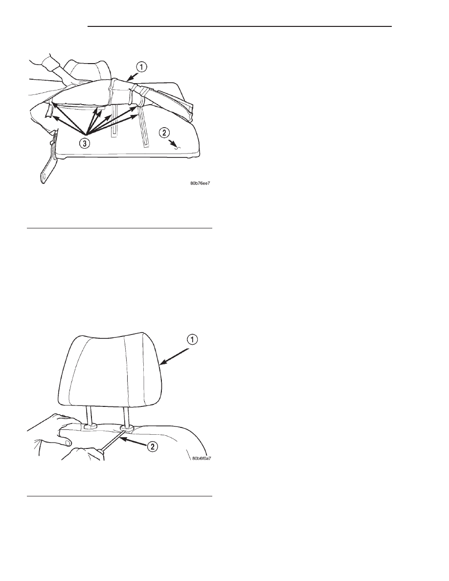
(2) Using a small flat blade, depress tab on out-

board side head rest release button and using your
hand, simultaneously press tab on inboard side head
rest release button (Fig. 14) and pull head rest up to
separate from seat back.

INSTALLATION

(1) Position head rest in seat back, press tab on

inboard side head rest release button cap and push
down head restraint to secure.

REAR SEAT FOLDING HEAD REST RELEASE
KNOB

The release knob is not salvageable during the

removal process The knob should only be replaced if
damaged or broken. Check availability before servic-
ing.

REMOVAL

(1) Using a E-XACTO knife or equivalent, cut the

release knob from the release lever.

(2) Pull the release knob from the lever (Fig. 15).

INSTALLATION

(1) Position the release knob on the lever and

press to snap in place.

REAR SEAT HEAD REST SLEEVE

REMOVAL

(1) Remove seat back.
(2) Remove head rest.
(3) Remove head rest caps.
(4) Remove seat back cover.
(5) Rotate head rest sleeve 1/4 turn counter-clock-

wise to release retaining tab.

(6) Pull sleeve from seat back frame.

INSTALLATION

(1) Position sleeve in seat back frame.
(2) Rotate head rest sleeve 1/4 turn clockwise to

engage retaining tab.

(3) Install seat back cover.
(4) Install head rest caps.

NOTE: The head rest cap with the taller button is
always on the inboard side of the seat back.

(5) Install the head rest.

NOTE: The

folding

head

rest

release

knob

is

always on the outboard side.

(6) Install the seat back.

REAR SEAT HEAD REST FOLDING
MECHANISM

REMOVAL

(1) Remove the head rest.
(2) Remove folding mechanism cover (Fig. 15).
(3) Remove the screws that secure the head rest

bun to the folding mechanism.

NOTE: The folding release knob is always located
on the outboard side.

Fig. 13 Rear Seat Back Cover

1 – SEAT BACK COVER
2 – SEAT BACK PAD
3 – HOOK AND LOOP FASTENER

Fig. 14 Head Rest

1 – HEAD RESTRAINT
2 – FLAT BLADE

23 - 22

BODY

WJ

REMOVAL AND INSTALLATION (Continued)

INSTALLATION

(1) Position the head rest bun on the folding mech-

anism and install the screws.

(2) Install the folding mechanism cover.
(3) Install the head restraint.

Fig. 15 Rear Seat Head Rest Folding Mechanism

1 – REAR SEAT HEAD REST FOLDING MECHANISM
2 – RELEASE KNOB
3 – FOLDING MECHANISM COVER

WJ

BODY

23 - 23

REMOVAL AND INSTALLATION (Continued)

BODY COMPONENTS

TABLE OF CONTENTS

page

page

DESCRIPTION AND OPERATION

BODY COMPONENTS . . . . . . . . . . . . . . . . . . . . . 25
COMPONENT FASTENERS . . . . . . . . . . . . . . . . . 25

DIAGNOSIS AND TESTING

WATER LEAKS . . . . . . . . . . . . . . . . . . . . . . . . . . 25
WIND NOISE . . . . . . . . . . . . . . . . . . . . . . . . . . . . 26
UNIVERSAL TRANSMITTER . . . . . . . . . . . . . . . . 27

SERVICE PROCEDURES

BODY LUBRICATION . . . . . . . . . . . . . . . . . . . . . . 27
DRILLING AND WELDING PROCEDURES . . . . . . 27

REMOVAL AND INSTALLATION

GRILLE . . . . . . . . . . . . . . . . . . . . . . . . . . . . . . . . 27
HOOD SEAL . . . . . . . . . . . . . . . . . . . . . . . . . . . . 28
HEADLAMP MOUNTING MODULE (HMM) . . . . . . 28
HOOD . . . . . . . . . . . . . . . . . . . . . . . . . . . . . . . . . 28
HOOD INSULATION PANEL . . . . . . . . . . . . . . . . . 29
HOOD SUPPORT PROP . . . . . . . . . . . . . . . . . . . 29
HOOD HINGE . . . . . . . . . . . . . . . . . . . . . . . . . . . 29
HOOD LATCH . . . . . . . . . . . . . . . . . . . . . . . . . . . 30
HOOD RELEASE CABLE . . . . . . . . . . . . . . . . . . . 30
COWL PLENUM SEAL . . . . . . . . . . . . . . . . . . . . . 31
COWL COVER . . . . . . . . . . . . . . . . . . . . . . . . . . . 31
EXTERIOR NAMEPLATES . . . . . . . . . . . . . . . . . . 31
SIDE VIEW MIRROR . . . . . . . . . . . . . . . . . . . . . . 32
SIDE VIEW MIRROR GLASS . . . . . . . . . . . . . . . . 32
FRONT FENDER . . . . . . . . . . . . . . . . . . . . . . . . . 33
FRONT DOOR TRIM PANEL . . . . . . . . . . . . . . . . 34
FRONT DOOR WATERDAM . . . . . . . . . . . . . . . . . 34
FRONT DOOR CHECK. . . . . . . . . . . . . . . . . . . . . 34
FRONT DOOR . . . . . . . . . . . . . . . . . . . . . . . . . . . 35
FRONT DOOR HINGE . . . . . . . . . . . . . . . . . . . . . 35
FRONT DOOR OUTSIDE HANDLE . . . . . . . . . . . . 36
FRONT DOOR LOCK CYLINDER . . . . . . . . . . . . . 36
LOCK CYLINDERS. . . . . . . . . . . . . . . . . . . . . . . . 37
FRONT DOOR LATCH . . . . . . . . . . . . . . . . . . . . . 37
FRONT DOOR LATCH STRIKER . . . . . . . . . . . . . 37
FRONT DOOR INSIDE HANDLE ACTUATOR . . . . 38
FRONT DOOR INNER BELT SEAL . . . . . . . . . . . . 38
FRONT DOOR OUTER BELT SEAL . . . . . . . . . . . 38
FRONT DOOR GLASS RUN CHANNEL

WEATHERSTRIP. . . . . . . . . . . . . . . . . . . . . . . . 38

FRONT DOOR GLASS RUN CHANNEL . . . . . . . . 39
FRONT DOOR OPENING WEATHERSTRIP . . . . . 39
FRONT DOOR SECONDARY WEATHERSTRIP . . 39
FRONT DOOR WINDOW REGULATOR . . . . . . . . 40
FRONT DOOR GLASS . . . . . . . . . . . . . . . . . . . . . 40
REAR DOOR B-PILLAR SEAL . . . . . . . . . . . . . . . 41
REAR DOOR TRIM PANEL. . . . . . . . . . . . . . . . . . 41
REAR DOOR WATERDAM . . . . . . . . . . . . . . . . . . 42

REAR DOOR CHECK. . . . . . . . . . . . . . . . . . . . . . 42
REAR DOOR . . . . . . . . . . . . . . . . . . . . . . . . . . . . 43
REAR DOOR HINGE . . . . . . . . . . . . . . . . . . . . . . 43
REAR DOOR OUTSIDE HANDLE . . . . . . . . . . . . . 44
REAR DOOR LATCH . . . . . . . . . . . . . . . . . . . . . . 44
REAR DOOR LATCH STRIKER . . . . . . . . . . . . . . 44
REAR DOOR INSIDE HANDLE ACTUATOR . . . . . 44
REAR DOOR INNER BELT WEATHERSTRIP . . . . 45
REAR DOOR OUTER BELT WEATHERSTRIP . . . 45
REAR DOOR OPENING WEATHERSTRIP . . . . . . 45
REAR DOOR SECONDARY WEATHERSTRIP . . . 46
REAR DOOR WINDOW REGULATOR . . . . . . . . . 46
REAR DOOR WINDOW GLASS . . . . . . . . . . . . . . 47
REAR DOOR STATIONARY GLASS . . . . . . . . . . . 47
ROOF RAIL WEATHERSTRIP W/RETAINER . . . . . 48
FUEL FILL DOOR. . . . . . . . . . . . . . . . . . . . . . . . . 48
BODY SIDE CLADDING . . . . . . . . . . . . . . . . . . . . 48
SILL MOLDING. . . . . . . . . . . . . . . . . . . . . . . . . . . 49
A-PILLAR TRIM . . . . . . . . . . . . . . . . . . . . . . . . . . 50
COWL LOWER TRIM . . . . . . . . . . . . . . . . . . . . . . 50
OVERHEAD ASSIST HANDLE . . . . . . . . . . . . . . . 51
FRONT DOOR SCUFF PLATE . . . . . . . . . . . . . . . 51
B-PILLAR UPPER TRIM . . . . . . . . . . . . . . . . . . . . 51
B-PILLAR LOWER TRIM. . . . . . . . . . . . . . . . . . . . 51
REAR DOOR SCUFF PLATE . . . . . . . . . . . . . . . . 52
C-PILLAR UPPER TRIM . . . . . . . . . . . . . . . . . . . . 53
QUARTER PANEL TRIM . . . . . . . . . . . . . . . . . . . . 53
STORAGE BIN . . . . . . . . . . . . . . . . . . . . . . . . . . . 54
UPPER LIFTGATE OPENING TRIM . . . . . . . . . . . 54
D-PILLAR TRIM . . . . . . . . . . . . . . . . . . . . . . . . . . 54
FRONT SHOULDER BELT . . . . . . . . . . . . . . . . . . 55
FRONT SHOULDER BELT BUCKLE . . . . . . . . . . . 55
REAR SEAT SHOULDER BELT . . . . . . . . . . . . . . 55
REAR SEAT BELT BUCKLE . . . . . . . . . . . . . . . . . 55
FLOOR CONSOLE . . . . . . . . . . . . . . . . . . . . . . . . 55
FRONT CARPET . . . . . . . . . . . . . . . . . . . . . . . . . 56
CARGO AREA CARPET . . . . . . . . . . . . . . . . . . . . 57
REARVIEW MIRROR . . . . . . . . . . . . . . . . . . . . . . 58
REARVIEW MIRROR SUPPORT BRACKET . . . . . 58
SUNVISOR. . . . . . . . . . . . . . . . . . . . . . . . . . . . . . 58
HEADLINER . . . . . . . . . . . . . . . . . . . . . . . . . . . . . 59
LIFTGATE TRIM PANEL . . . . . . . . . . . . . . . . . . . . 60
LOWER LIFTGATE OPENING TRIM PANEL . . . . . 60
LIFTGATE INSULATOR . . . . . . . . . . . . . . . . . . . . 60
LIFTGATE . . . . . . . . . . . . . . . . . . . . . . . . . . . . . . 61
LIFTGATE HINGE. . . . . . . . . . . . . . . . . . . . . . . . . 62
LIFTGATE OUTSIDE HANDLE . . . . . . . . . . . . . . . 62
LIFTGATE LATCH . . . . . . . . . . . . . . . . . . . . . . . . 62
LIFTGATE LATCH STRIKER . . . . . . . . . . . . . . . . . 62

23 - 24

BODY

WJ

LIFTGATE OPENING WEATHERSTRIP . . . . . . . . 63
FLIP UP GLASS . . . . . . . . . . . . . . . . . . . . . . . . . . 64
FLIP UP GLASS WEATHERSTRIP . . . . . . . . . . . . 64
FLIP UP GLASS SWITCH. . . . . . . . . . . . . . . . . . . 64
FLIP UP GLASS LATCH . . . . . . . . . . . . . . . . . . . . 64
FLIP UP GLASS LATCH STRIKER . . . . . . . . . . . . 66
LICENSE PLATE LAMP HOUSING . . . . . . . . . . . . 66
D-PILLAR APPLIQUE . . . . . . . . . . . . . . . . . . . . . . 66
D-PILLAR AIR EXHAUSTER . . . . . . . . . . . . . . . . . 66
TAIL LAMP AIR EXHAUSTER . . . . . . . . . . . . . . . . 66
LUGGAGE RACK . . . . . . . . . . . . . . . . . . . . . . . . . 67

ADJUSTMENTS

HOOD ADJUSTMENT. . . . . . . . . . . . . . . . . . . . . . 67

DOOR ADJUSTMENT. . . . . . . . . . . . . . . . . . . . . . 67
DOOR LATCH . . . . . . . . . . . . . . . . . . . . . . . . . . . 67
LIFTGATE ADJUSTMENT . . . . . . . . . . . . . . . . . . . 67

SPECIFICATIONS

BODY LUBRICANTS . . . . . . . . . . . . . . . . . . . . . . 68
WELD LOCATIONS . . . . . . . . . . . . . . . . . . . . . . . 69
SEALER LOCATIONS . . . . . . . . . . . . . . . . . . . . . 118
STRUCTURAL ADHESIVE LOCATIONS . . . . . . . 135
BODY GAP AND FLUSH MEASUREMENTS . . . . 151
BODY OPENING DIMENSIONS . . . . . . . . . . . . . 153
TORQUE SPECIFICATIONS . . . . . . . . . . . . . . . . 156

SPECIAL TOOLS

BODY. . . . . . . . . . . . . . . . . . . . . . . . . . . . . . . . . 156

DESCRIPTION AND OPERATION

BODY COMPONENTS

DESCRIPTION

Exterior sheet metal components make up the

exterior of the vehicle. Some exterior metal systems
are welded assemblies, such as doors and hoods.
Some exterior trim items are made of composite.

OPERATION

The exterior is finished in various metal stampings

and composite moldings. These assemblies give the
vehicle a finished appearance and protect the occu-
pants from the elements. Some components are part
of the energy absorbing system used to protect the
occupants in collisions. The exterior sheet metal is
repairable and adjustable for fit and finish. Welded
and bonded component systems are adjustable as a
system. Trim components made of composite are
stamped with the type of material used. Daimler-
Chrysler uses various fasteners to retain trim items.
At times, it is not possible to remove trim items
without damaging the fastener. If it is not possible to
remove an item without damaging a component, cut
or break the fasteners and use new ones when
installing the component.

COMPONENT FASTENERS

DaimlerChrysler Corporation uses many different

types of push-in fasteners to secure the interior and
exterior trim to the body. Most of these fasteners can
be reused to assemble the trim during various repair
procedures. At times, a push-in fastener cannot be
removed without damaging the fastener or the com-
ponent it is holding. If it is not possible to remove a
fastener without damaging a component or body, cut
or break the fastener and use a new one when
installing the component. Never pry or pound on a
plastic or pressed-board trim component. Using a
suitable fork-type prying device, pry the fastener
from the retaining hole behind the component being

removed. When installing, verify fastener alignment
with the retaining hole by hand. Push directly on or
over the fastener until it seats. Apply a low-force pull
to the panel to verify that it is secure.

When it is necessary to remove components to ser-

vice another, it should not be necessary to apply
excessive force or bend a component to remove it.
Before damaging a trim component, verify hidden
fasteners or captured edges holding the component in
place.

DIAGNOSIS AND TESTING

WATER LEAKS

Water leaks can be caused by poor sealing,

improper body component alignment, body seam
porosity, missing plugs, or blocked drain holes. Cen-
trifugal and gravitational force can cause water to
drip from a location away from the actual leak point,
making leak detection difficult. All body sealing
points should be water tight in normal wet-driving
conditions. Water flowing downward from the front of
the vehicle should not enter the passenger or luggage
compartment.

Moving

sealing

surfaces

will

not

always seal water tight under all conditions. At
times, side glass or door seals will allow water to
enter the passenger compartment during high pres-
sure washing or hard driving rain (severe) condi-
tions.

Overcompensating

on

door

or

glass

adjustments to stop a water leak that occurs under
severe conditions can cause premature seal wear and
excessive closing or latching effort. After completing
a repair, water test vehicle to verify leak has stopped
before returning vehicle to use.

VISUAL INSPECTION BEFORE WATER LEAK TESTS

Verify that floor and body plugs are in place, body

drains are clear, and body components are properly
aligned and sealed. If component alignment or seal-
ing is necessary, refer to the appropriate section of
this group for proper procedures.

WJ

BODY

23 - 25


Content   ..  529  530  531  532   ..