Jeep Grand Cherokee WJ. Manual - part 99


  Index      Jeep     Jeep Grand Cherokee WJ - service repair manual 2001 year


Search            


Content   ..  97  98  99  100   ..


Jeep Grand Cherokee WJ. Manual - part 99


not force it. Remove switch from housing and rotate
key cylinder (slightly) for alignment. Push switch
into column housing until 2 lock tabs have engaged.

(6) Install ignition switch mounting screw. Tighten

screw to 3 N·m (30 in. lbs.) torque.

(7) Connect electrical connectors to ignition switch.

Make sure that switch locking tabs are fully seated
in wiring connectors.

(8) Install SKIM (Sentry Key Immobilizer Module)

(1 screw). Tighten screw to 3 N·m (30 in. lbs.) torque.

(9) Install steering column covers (shrouds).
(10) Connect negative cable to battery.
(11) Shifter should lock in PARK position when

key is in LOCK position. Shifter should unlock when
key rotated to ON position.

(12) With engine running, shifter should not be

unable to be moved from PARK position until brake
pedal has been depressed.

(13) Check for proper operation of ignition switch

in ACCESSORY, LOCK, OFF, ON, RUN, and START
positions.

(14) Steering wheel should lock when key is in

LOCK position. Rotate steering wheel to verify.
Steering wheel should unlock when key is rotated to
ON position.

SHIFTER/IGNITION INTERLOCK

REMOVAL/INSTALLATION

On models equipped with an automatic transmis-

sion, a cable connects the ignition switch with the
floor shift lever. The shifter will be locked in the
PARK position when the ignition key is in the LOCK
or ACCESSORY positions. The cable can be adjusted
or replaced. Refer to Group 21, Transmissions for
procedures. The ignition interlock device within the
steering column is not serviceable. If service is nec-
essary, the steering column must be replaced. Refer
to Group 19, Steering for procedures.

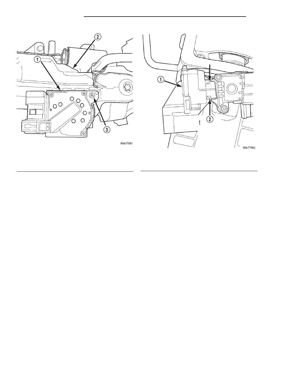
Fig. 41 Ignition Switch Lock Tabs

1 – IGNITION SWITCH
2 – SQUEEZE BOTH TABS FOR REMOVAL

Fig. 40 Ignition Switch Mounting Screw

1 – IGNITION SWITCH
2 – STEERING COLUMN
3 – SWITCH MOUNTING SCREW

8D - 20

IGNITION SYSTEM

WJ

REMOVAL AND INSTALLATION (Continued)

SPECIFICATIONS

IGNITION TIMING

All ignition timing functions are controlled by the

Powertrain

Control

Module

(PCM).

Mechanical

adjustments are not needed and can’t be made.

On the 4.0L 6–cylinder engine, do not attempt to

rotate the oil pump drive to adjust timing. This
adjustment is used for fuel synchronization after
camshaft position sensor replacement.

ENGINE FIRING ORDER—4.0L 6-CYLINDER
ENGINE

ENGINE FIRING ORDER—4.7L V-8 ENGINE

WJ

IGNITION SYSTEM

8D - 21

SPARK PLUGS

ENGINE

PLUG TYPE

ELECTRODE GAP

4.0L 6-CYL.

RC12ECC

0.89 mm (.035 in.)

4.7L V-8

RC12MCC4

1.01 mm (.040 in.)

IGNITION COIL RESISTANCE—4.0L ENGINE

PRIMARY RESISTANCE

21-27°C (70-80°F)

0.71 - 0.88 Ohms

IGNITION COIL RESISTANCE—4.7L V-8
ENGINE

PRIMARY RESISTANCE

21-27°C (70-80°F)

SECONDARY

RESISTANCE 21-27°C

(70-80°F)

0.6 - 0.9 Ohms

6,000 - 9,000 Ohms

TORQUE CHART

DESCRIPTION

TORQUE

Crankshaft Position Sensor

Bolts—4.0L Engine . . . . . . . . . 7 N·m (60 in. lbs.)

Crankshaft Position Sensor

Bolt—4.7L V-8 Engine . . . . . . 28 N·m (21 ft. lbs.)

Camshaft Position Sensor–to–base bolts—4.0L

Engine . . . . . . . . . . . . . . . . . 28 N·m (15 in. lbs.)

Camshaft Position Sensor

Bolt—4.7L V-8 Engine . . . . 12 N·m (106 in. lbs.)

Oil Pump Drive Hold-down

Bolt—4.0L Engine . . . . . . . . . 23 N·m (17 ft. lbs.)

Ignition Coil Rail Mounting

Bolts—4.0L Engine . . . . . . . 29 N·m (250 in. lbs.)

Ignition Coil Mounting

Nut—4.7L V-8 Engine . . . . . . 8 N·m (70 in. lbs.)

Spark Plugs—4.0L

Engine . . . . . . . . . . . . 35–41 N·m (26–30 ft. lbs.)

Spark Plugs—4.7L V-8

Engine . . . . . . . . . . . . . . . . . . 27 N·m (20 ft. lbs.)

8D - 22

IGNITION SYSTEM

WJ

SPECIFICATIONS (Continued)

INSTRUMENT PANEL SYSTEMS

TABLE OF CONTENTS

page

page

DESCRIPTION AND OPERATION

INSTRUMENT PANEL SYSTEM . . . . . . . . . . . . . . 1
INSTRUMENT PANEL . . . . . . . . . . . . . . . . . . . . . . 2
INSTRUMENT CLUSTER. . . . . . . . . . . . . . . . . . . . 3
BODY CONTROL MODULE . . . . . . . . . . . . . . . . . . 5
CIGAR LIGHTER RELAY . . . . . . . . . . . . . . . . . . . . 6
INSTRUMENT PANEL CIGAR LIGHTER . . . . . . . . 6
INSTRUMENT PANEL POWER OUTLET . . . . . . . . 6

DIAGNOSIS AND TESTING

INSTRUMENT CLUSTER. . . . . . . . . . . . . . . . . . . . 7
BODY CONTROL MODULE . . . . . . . . . . . . . . . . . . 9
CIGAR LIGHTER RELAY . . . . . . . . . . . . . . . . . . . . 9
INSTRUMENT PANEL CIGAR LIGHTER . . . . . . . . 9
INSTRUMENT PANEL POWER OUTLET . . . . . . . 10

REMOVAL AND INSTALLATION

INSTRUMENT PANEL FUSE COVER. . . . . . . . . . 11
BODY CONTROL MODULE . . . . . . . . . . . . . . . . . 12
INSTRUMENT PANEL DRIVER SIDE BEZEL. . . . 13
INSTRUMENT PANEL DRIVER SIDE

COURTESY LAMP BRACKET . . . . . . . . . . . . . . 13

CLUSTER BEZEL. . . . . . . . . . . . . . . . . . . . . . . . . 14
INSTRUMENT PANEL STEERING COLUMN

BRACKET . . . . . . . . . . . . . . . . . . . . . . . . . . . . . 15

STEERING COLUMN OPENING COVER . . . . . . . 15
INSTRUMENT CLUSTER. . . . . . . . . . . . . . . . . . . 16
INSTRUMENT CLUSTER COMPONENTS . . . . . . 17
INSTRUMENT PANEL CENTER UPPER BEZEL. . 20
INSTRUMENT PANEL CENTER LOWER

BEZEL . . . . . . . . . . . . . . . . . . . . . . . . . . . . . . . 21

INSTRUMENT PANEL CIGAR LIGHTER AND

POWER OUTLET . . . . . . . . . . . . . . . . . . . . . . . 21

CIGAR LIGHTER RELAY . . . . . . . . . . . . . . . . . . . 22
INSTRUMENT PANEL POWER OUTLET

DOOR. . . . . . . . . . . . . . . . . . . . . . . . . . . . . . . . 23

GLOVE BOX . . . . . . . . . . . . . . . . . . . . . . . . . . . . 24
INSTRUMENT PANEL TO CENTER FLOOR

TUNNEL BRACKET . . . . . . . . . . . . . . . . . . . . . 24

INSTRUMENT PANEL END CAP . . . . . . . . . . . . . 26
GLOVE BOX LATCH . . . . . . . . . . . . . . . . . . . . . . 26
INSTRUMENT PANEL LOWER RIGHT

CENTER BEZEL . . . . . . . . . . . . . . . . . . . . . . . . 27

GLOVE BOX LAMP AND SWITCH . . . . . . . . . . . 28
GLOVE BOX LATCH STRIKER . . . . . . . . . . . . . . 28
INSTRUMENT PANEL TOP COVER. . . . . . . . . . . 29
INSTRUMENT PANEL TOP PAD . . . . . . . . . . . . . 30
INSTRUMENT PANEL PASSENGER SIDE

BEZEL . . . . . . . . . . . . . . . . . . . . . . . . . . . . . . . 33

INSTRUMENT PANEL ASSEMBLY . . . . . . . . . . . 34
INSTRUMENT PANEL C-CHANNEL COVER

BRACKET . . . . . . . . . . . . . . . . . . . . . . . . . . . . . 41

INSTRUMENT PANEL INTERMEDIATE

BRACKET . . . . . . . . . . . . . . . . . . . . . . . . . . . . . 42

INSTRUMENT PANEL PLENUM BRACKET . . . . . 43
INSTRUMENT PANEL STEERING COLUMN

SUPPORT BRACKET . . . . . . . . . . . . . . . . . . . . 43

INSTRUMENT PANEL STRUCTURAL DUCT . . . . 44

DESCRIPTION AND OPERATION

INSTRUMENT PANEL SYSTEM

DESCRIPTION

The instrument panel serves as the command cen-

ter of the vehicle, which necessarily makes it a very
complex unit. The instrument panel is designed to
house the controls and monitors for standard and
optional powertrains, climate control systems, audio
systems, lighting systems, safety systems and many
other comfort or convenience items. The instrument
panel is also designed so that all of the various con-
trols can be safely reached and the monitors can be

easily viewed by the vehicle operator when driving,
while still allowing relative ease of access to each of
these items for service. See the owner’s manual in
the vehicle glove box for more information on the fea-
tures, use and operation of all of the instrument
panel components and systems.

This group is responsible for covering service infor-

mation for the vehicle instrument panel systems.
However, complete service information coverage for
all of the systems and components housed in the
instrument panel in a single section of the service
manual would not be practical. Therefore, the service
information for any component will be found in the
group designated to cover the vehicle system that the

WJ

INSTRUMENT PANEL SYSTEMS

8E - 1


Content   ..  97  98  99  100   ..