Jeep Grand Cherokee WJ. Manual - part 98


  Index      Jeep     Jeep Grand Cherokee WJ - service repair manual 2001 year


Search            


Content   ..  96  97  98  99   ..


Jeep Grand Cherokee WJ. Manual - part 98


REMOVAL—SENSOR ONLY

(1) Disconnect electrical connector at CMP sensor

(Fig. 32).

(2) Remove 2 sensor mounting bolts (Fig. 31) or

(Fig. 32).

(3) Remove sensor from oil pump drive.

INSTALLATION—SENSOR ONLY

(1) Install sensor to oil pump drive.
(2) Install 2 sensor mounting bolts and tighten to

2 N·m (15 in. lbs.) torque.

(3) Connect electrical connector to CMP sensor.

REMOVAL—OIL PUMP DRIVE AND SENSOR

If the CMP and oil pump drive are to be

removed and installed, do not allow engine
crankshaft or camshaft to rotate. CMP sensor
relationship will be lost.

(1) Disconnect electrical connector at CMP sensor

(Fig. 32).

(2) Remove 2 sensor mounting bolts (Fig. 31) or

(Fig. 32).

(3) Remove sensor from oil pump drive.

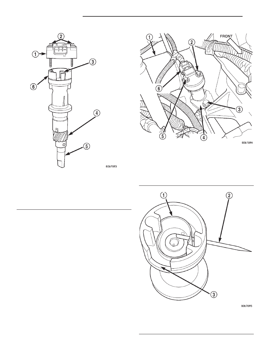
Fig. 31 CMP and Oil Pump Drive Shaft—4.0L Engine

1 – CAMSHAFT POSITION SENSOR
2 – MOUNTING BOLTS (2)
3 – PULSE RING
4 – DRIVE GEAR (TO CAMSHAFT)
5 – OIL PUMP DRIVESHAFT
6 – SENSOR BASE (OIL PUMP DRIVESHAFT ASSEMBLY)

Fig. 32 CMP Location—4.0L Engine

1 – OIL FILTER
2 – CAMSHAFT POSITION SENSOR
3 – CLAMP BOLT
4 – HOLD-DOWN CLAMP
5 – MOUNTING BOLTS (2)
6 – ELEC. CONNECTOR

Fig. 33 CMP Pulse Ring Alignment—4.0L Engine

1 – PULSE RING (SHUTTER)
2 – TOOTHPICK
3 – SENSOR BASE (OIL PUMP DRIVESHAFT ASSEMBLY)

8D - 16

IGNITION SYSTEM

WJ

REMOVAL AND INSTALLATION (Continued)

(4) Before proceeding to next step, mark and note

rotational position of oil pump drive in relationship
to engine block. After installation, the CMP sensor
should face rear of engine 0°.

(5) Remove hold-down bolt and clamp (Fig. 32).
(6) While pulling assembly from engine, note direc-

tion and position of pulse ring (Fig. 31). After
removal, look down into top of oil pump and note
direction and position of slot at top of oil pump gear.

(7) Remove and discard old oil pump drive-to-en-

gine block gasket.

INSTALLATION—OIL PUMP DRIVE AND SENSOR

(1) Clean oil pump drive mounting hole area of

engine block.

(2) Install new oil pump drive-to-engine block gas-

ket.

(3) Temporarily install a toothpick or similar tool

through access hole at side of oil pump drive housing.
Align toothpick into mating hole on pulse ring (Fig.
33).

(4) Install oil pump drive into engine while align-

ing into slot on oil pump. Rotate oil pump drive back
to its original position and install hold-down clamp
and bolt. Finger tighten bolt. Do not do a final tight-
ening of bolt at this time.

(5) If engine crankshaft or camshaft has been

rotated, such as during engine tear-down, CMP sen-
sor relationship must be reestablished.

(a) Remove ignition coil rail assembly. Refer to

Ignition Coil Removal/Installation.

(b) Remove cylinder number 1 spark plug.
(c) Hold a finger over the open spark plug hole.

Rotate engine at vibration dampener bolt until
compression (pressure) is felt.

(d) Slowly continue to rotate engine. Do this

until timing index mark on vibration damper pul-
ley aligns with top dead center (TDC) mark
(0 degree) on timing degree scale (Fig. 34). Always
rotate engine in direction of normal rotation. Do
not rotate engine backward to align timing marks.

(e) Install oil pump drive into engine while

aligning into slot on oil pump. If pump drive will
not drop down flush to engine block, the oil pump
slot is not aligned. Remove oil pump drive and
align slot in oil pump to shaft at bottom of drive.
Install into engine. Rotate oil pump drive back to
its original position and install hold-down clamp
and bolt. Finger tighten bolt. Do not do a final
tightening of bolt at this time.

(f) Remove toothpick from housing.

(6) Install sensor to oil pump drive. After installa-

tion, the CMP sensor should face rear of engine 0°.

(7) Install 2 sensor mounting bolts and tighten to

2 N·m (15 in. lbs.) torque.

(8) Connect electrical connector to CMP sensor.
(9) If removed, install spark plug and ignition coil

rail.

To verify correct rotational position of oil pump

drive, the DRB scan tool must be used.

WARNING: WHEN PERFORMING THE FOLLOWING
TEST, THE ENGINE WILL BE RUNNING. BE CARE-
FUL NOT TO STAND IN LINE WITH THE FAN
BLADES OR FAN BELT. DO NOT WEAR LOOSE
CLOTHING.

(10) Connect DRB scan tool to data link connector.

The data link connector is located in passenger com-
partment, below and to left of steering column.

(11) Gain access to SET SYNC screen on DRB.
(12) Follow directions on DRB screen and start

engine. Bring to operating temperature (engine must
be in “closed loop” mode).

(13) With engine running at idle speed, the words

IN RANGE should appear on screen along with 0°.
This indicates correct position of oil pump drive.

(14) If a plus (+) or a minus (-) is displayed next to

degree number, and/or the degree displayed is not
zero, loosen but do not remove hold-down clamp bolt.
Rotate oil pump drive until IN RANGE appears on
screen. Continue to rotate oil pump drive until
achieving as close to 0° as possible.

The degree scale on SET SYNC screen of DRB is

referring to fuel synchronization only. It is not
referring to ignition timing. 
Because of this, do
not attempt to adjust ignition timing using this
method. Rotating oil pump drive will have no effect

Fig. 34 Align Timing Marks—4.0L Engine

1 – CRANKSHAFT VIBRATION DAMPER TIMING MARK

WJ

IGNITION SYSTEM

8D - 17

REMOVAL AND INSTALLATION (Continued)

on ignition timing. All ignition timing values are con-
trolled by powertrain control module (PCM).

(15) Tighten hold-down clamp bolt to 23 N·m (17

ft. lbs.) torque.

CAMSHAFT POSITION SENSOR—4.7L ENGINE

The Camshaft Position Sensor (CMP) on the 4.7L

V–8 engine is bolted to the front/top of the right cyl-
inder head (Fig. 35).

REMOVAL

It is easier to remove/install sensor from under

vehicle.

(1) Raise and support vehicle.
(2) Disconnect electrical connector at CMP sensor

(Fig. 35).

(3) Remove sensor mounting bolt (Fig. 35).
(4) Carefully pry sensor from cylinder head in a

rocking action with two small screwdrivers.

(5) Check condition of sensor o-ring.

INSTALLATION

(1) Clean out machined hole in cylinder head.
(2) Apply a small amount of engine oil to sensor

o-ring.

(3) Install sensor into cylinder head with a slight

rocking action. Do not twist sensor into position as
damage to o-ring may result.

CAUTION: Before tightening sensor mounting bolt,
be sure sensor is completely flush to cylinder head.
If sensor is not flush, damage to sensor mounting
tang may result.

(4) Install mounting bolt and tighten to 12 N·m

(106 in. lbs.) torque.

(5) Connect electrical connector to sensor.
(6) Lower vehicle.

IGNITION SWITCH AND KEY CYLINDER

The ignition key must be in key lock cylinder for

cylinder removal.

REMOVAL

If removing key lock cylinder only, refer to first

6 steps. If removing ignition switch only, refer to
steps 1 and 2 and proceed to steps 7 through 13.

(1) Disconnect negative cable from battery.
(2) Place transmission shifter in PARK position.
(3) Place tilt steering wheel in full up position.
(4) A retaining pin (Fig. 36) is located at bottom of

key lock cylinder housing.

(5) Rotate key to RUN position.
(6) Press in on retaining pin while pulling key cyl-

inder from housing. After removal, note position of
alignment tang at end of cylinder. When installing
lock cylinder, key must be rotated back to RUN posi-
tion.

Fig. 35 CMP Location—4.7L Engine

1 – RIGHT CYLINDER HEAD
2 – CAMSHAFT POSITION SENSOR
3 – MOUNTING BOLT
4 – ELEC. CONNECTOR

Fig. 36 Retaining Pin

1 – BOTTOM OF STEERING COLUMN
2 – KEY LOCK CYLINDER
3 – RETAINING PIN
4 – LOCK CYLINDER HOUSING

8D - 18

IGNITION SYSTEM

WJ

REMOVAL AND INSTALLATION (Continued)

(7) Remove steering column lower opening cover.

Refer to Steering Column Opening Cover in Group
8E, Instrument Panel.

(8) Remove upper and lower covers (shrouds) from

steering column (Fig. 37).

(9) Remove upper fixed column shroud (2 screws)

(Fig. 38).

(10) Remove SKIM (Sentry Key Immobilizer Mod-

ule) (1 screw) (Fig. 39).

(11) Disconnect electrical connectors at switch.
(12) Remove ignition switch mounting screw (Fig.

40). Use tamper proof torx bit (Snap-On

t TTXR10E

or equivalent) to remove screw.

(13) Using needle-nose pliers, squeeze both switch

lock tabs (Fig. 41) and gently pull switch away from
column. Do not rotate key lock cylinder when
ignition switch is being removed or has been
removed from steering column.

INSTALLATION

If installing key lock cylinder only, refer to steps

1 through 4 then proceed to steps 10 through 14. If
installing ignition switch only, refer to steps 5
through 14.

(1) Be sure transmission shifter is still in PARK

position.

(2) Rotate key in lock cylinder to RUN position.
(3) Install key cylinder into housing by aligning

retaining pin into retaining pin slot. Push key cylin-
der into housing until retaining pin engages. After
pin engages, rotate key to OFF or LOCK position.

(4) Check for proper retention of key cylinder by

attempting to pull cylinder from housing.

(5) Place ignition switch into opening on steering

column housing. If switch will not fit into housing, do

Fig. 37 Shroud Removal/Installation

1 – UPPER TILTING COLUMN SHROUD
2 – FIXED COLUMN SHROUD
3 – LOWER TILTING COLUMN SHROUD
4 – SCREW

Fig. 38 Fixed Column Shroud Removal/Installation

1 – UPPER FIXED SHROUD
2 – COLUMN

Fig. 39 Sentry Key Immobilizer Module and

Mounting Screw

1 – STEERING COLUMN
2 – SKIM
3 – MOUNTING SCREW

WJ

IGNITION SYSTEM

8D - 19

REMOVAL AND INSTALLATION (Continued)


Content   ..  96  97  98  99   ..