Jaguar X-Type Sedan and Estate (Wagon). Manual - part 509


  Index      Jaguar     Jaguar X-Type Sedan and Estate (Wagon) (2.0 L, 2.5 L and 3.0 L Gasoline; 2.0 L and 2.2 L, Diesel) - manual 2001-2009 year


Search            


Content   ..  507  508  509  510   ..


Jaguar X-Type Sedan and Estate (Wagon). Manual - part 509


Published: 11-May-2011

Control Components - Air Discharge Temperature Sensor

Removal and Installation

Removal

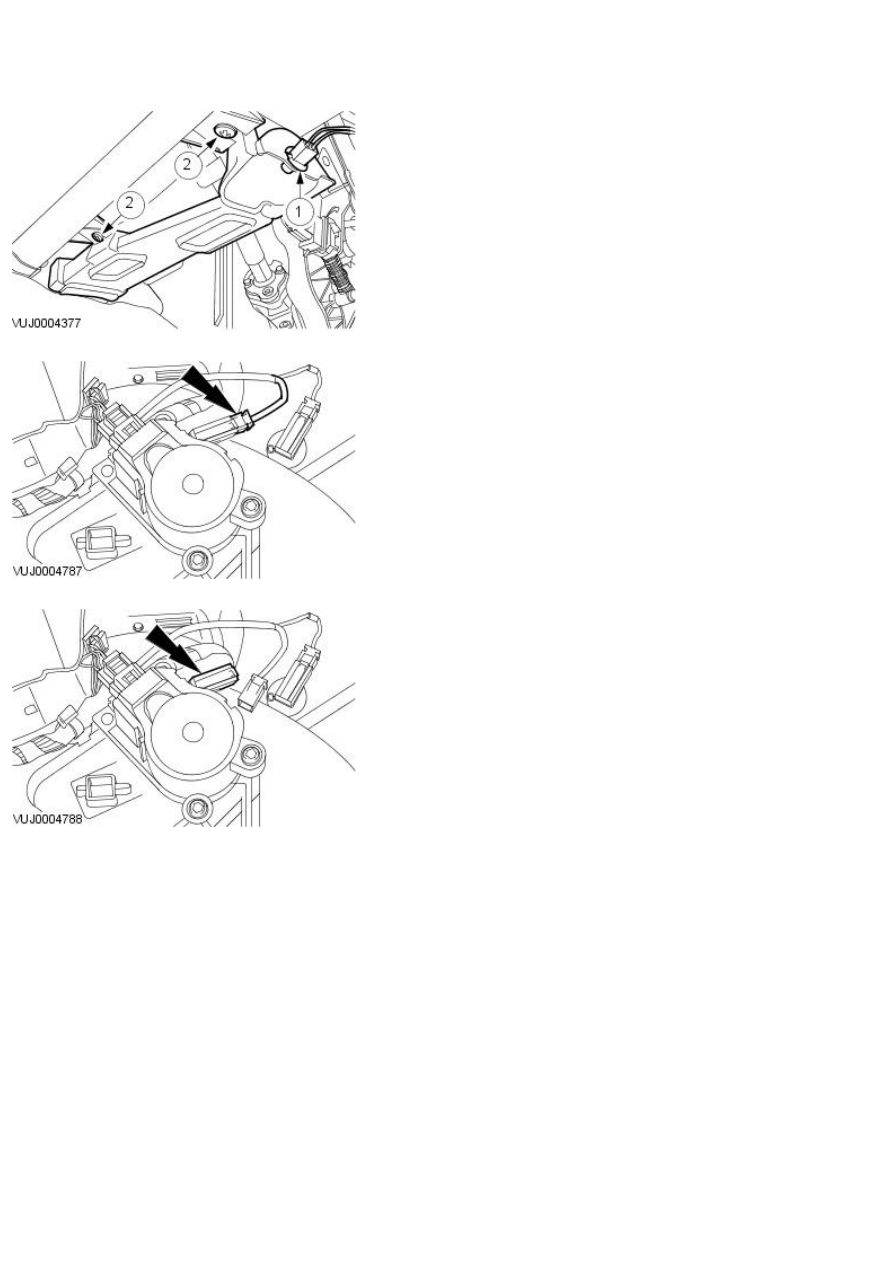
1. Remove the lower vent.

1. Detach the bulb holder.

2. Remove the lower vent.

2. Disconnect the air discharge temperature sensor electrical connector.

3. Remove the air discharge temperature sensor.

Installation

1. To install, reverse the removal procedure.

Published: 11-May-2011

Control Components - Ambient Air Temperature Sensor

Removal and Installation

Removal

CAUTION: Make sure the ignition switch is in the off position before disconnecting the ambient air temperature sensor.

1. Detach the ambient air temperature sensor from the power assisted

steering cooler bracket.

2. Remove the ambient air temperature sensor.

Disconnect the electrical connector.

Installation

1. To install, reverse the removal procedure.

Published: 11-May-2011

Control Components - Climate Control Assembly

Removal and Installation

Removal

Vehicles with automatic transaxle

1. NOTE: To aid removal of the climate control assembly place the J-gate
selector in the neutral position.

Remove the J-gate surround.

Vehicles with manual transaxle

2. Detach the gear selector surround.

All vehicles

3. Disconnect the battery ground cable. For additional information, refer to

Section

 414-01 Battery, Mounting and Cables

.

4. Remove the ashtray retaining screws.

5. Remove the ashtray.

Disconnect the electrical connectors.

6. Remove the climate control assembly mounting bracket upper retaining

screws cover.

7. Remove the climate control assembly mounting bracket upper retaining

screws.

8. Remove the climate control assembly mounting bracket lower retaining

screws.

9. Disconnect the hazard lamp switch assembly electrical connectors.

10. Remove the hazard lamp switch assembly.

Remove the retaining screws.


Content   ..  507  508  509  510   ..