JAC S2 (Chassis). Service Manual - part 4


  Index      JAC     JAC S2 (Chassis). Service Manual


Search            copyright infringement  


Content      ..     2      3      4      5     ..


JAC S2 (Chassis). Service Manual - part 4


Clutch


Clutch   


            37 

2. Drain clutch hydraulic oil, refers to clutch hydraulic oil  
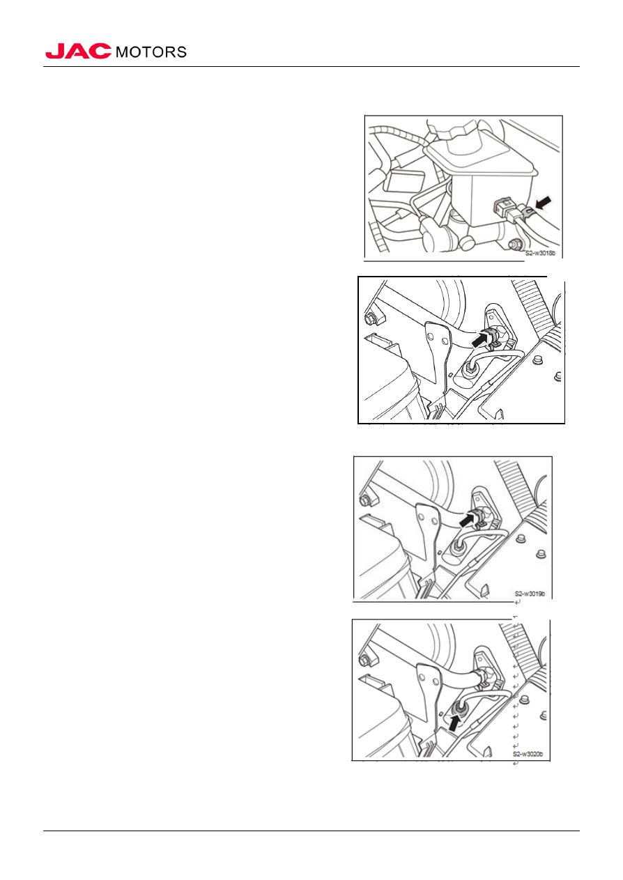
3. Remove the inlet pipe assembly 

1). Remove the clip, disengage inlet pipe assembly 
and brake master cylinder. 


2).  Remove the clip, disengage inlet pipe assembly and 
clutch master cylinder. 

3) Remove the inlet pipe assembly. 


4. Remove the clutch master cylinder 

1).  Removing the clip, disengage inlet pipe assembly 
and clutch master cylinder. 


2) Remove the flare nut and disengage the clutch 
hard pipe assembly - I and clutch master cylinder. 


-------------------------------------------------------------------------------------------------------------------------------------------------------------


Clutch


Clutch   


            38 


3). Remove the clamp connecting the clutch pedal and 
clutch master cylinders, remove the latch, disengage the 
clutch pedal and the clutch master cylinder. 


4) Remove the two fixing nuts connecting clutch master 
cylinder and clutch pedal body. 

5) Remove the clutch master cylinder. 


 (II) Installation 

1. Install the clutch master cylinder 

1).  Place the clutch master cylinder to the installation 
location. 

2) Install the two fixing nuts connecting clutch master 
cylinder and clutch pedal body. 
Tighten torque 20 ~ 28N • m 


3) Install the lock pin, install clamp connecting clutch 
pedal and the clutch master cylinder.  
△ Note Coat low temperature grease Kunlun II on the 
outer surface of the front pin.  


4). Install nut connecting the clutch hard pipe assembly 

- Ⅰ and clutch master cylinder. 

Tightening torque 16 ~ 18N • m 


-------------------------------------------------------------------------------------------------------------------------------------------------------------


Clutch


Clutch   


            39 


5).  Install clamps to connecting clutch master 
cylinder inlet pipe assembly and the clutch master 
cylinder. 


2. Install the inlet pipe assembly 

1).  Install clamp to connect inlet pipe assembly and 
brake master cylinder. 


2) Install clamp to connect inlet pipe assembly clutch 
master cylinder. 

3. Fill the clutch hydraulic oil refers to clutch 
hydraulic oil 
4. Drain clutch system refers to the clutch hydraulic oil 
5. Close the engine hatch 


VIII Clutch cylinder and the inlet pipe assembly 

(I) Remove 

1. Open the engine hatch 
2. Drain clutch hydraulic oil refers to clutch hydraulic oil  
3. Remove the clutch inlet pipe assembly 


-------------------------------------------------------------------------------------------------------------------------------------------------------------


Clutch


Clutch   


            40 


1) Remove connection nut between the clutch inlet 
pipe and the clutch hard tube assembly 


2). Remove the fixing nut connecting clutch inlet pipe 
and clutch working cylinder. 

3). Disengage clutch inlet pipe assembly 


4. Remove clutch cylinder 

1). Remove bolts connecting the clutch inlet pipe and 
the clutch cylinder. 


2). Remove the latch and rivets connecting the clutch 
cylinder and separation fork. 


-------------------------------------------------------------------------------------------------------------------------------------------------------------


Clutch


Clutch   


            41 


3) Remove the two fixing bolts connecting the clutch 
cylinder and the gearbox. 

4) Remove the clutch cylinder. 


(II) Installation 

1. Install clutch cylinder 

1). Connect the latch and rivets to the clutch cylinder 
and separation fork 


2).  Install fixing bolts connecting the clutch inlet pipe 
and the clutch cylinder 


3). Install two fixing bolts to connect the clutch 
cylinder and the gearbox. 
Tightening torque 14.7 ~ 21.6N • m 


-------------------------------------------------------------------------------------------------------------------------------------------------------------


Clutch


Clutch   


            42 


2. Install the clutch inlet pipe assembly 

1) Install the fixing bolts to connect the clutch inlet 
pipe and the clutch cylinder. 


2) Install the connection nut between the clutch inlet 

pipe and the clutch hard tube assembly - Ⅰ. 

Tightening torque 16 ~ 18N • m 


3. Fill the clutch hydraulic oil refers to clutch hydraulic 
oil  
4. Drain clutch system refers to the clutch hydraulic oil 
5. Close the engine hatch 

IX Clutch hard pipe assembly 

(I) Remove 

1. Open the engine hatch 
2. Drain clutch hydraulic oil refers to the clutch 
hydraulic oil  
3. Remove clutch hard tube assembly 

1) Remove the connection nut between the clutch inlet 
pipe and the clutch hard tube assembly 


2) Remove the pipe nut and the connection between the 
clutch hard pipe assembly and clutch master cylinder. 

3) Remove the clutch hard tube assembly 


-------------------------------------------------------------------------------------------------------------------------------------------------------------


Clutch


Clutch   


            43 


 (II). Installation 

1. Install the clutch hard tube assembly 

1) Install oil pipe nuts and remove the connection 

between clutch hard pipe assembly - Ⅰ and clutch master 

cylinder. 
Tightening torque 16 ~ 18N • m 


2) Install the connection nut between the clutch inlet 

pipe and the clutch hard tube assembly - Ⅰ 

Tightening torque 20 ~ 28N • m 


2. Fill the clutch hydraulic oil refers to clutch hydraulic 
oil 
3. Drain clutch system refers to clutch hydraulic oil 
4. Close the engine hatch 

 
X Clutch cover and pressure plate assembly, clutch driven disc 

(I) Remove 

1. Remove the transmission assembly refers to gearbox assembly  
2. Remove the clutch cover and pressure plate assembly, 
clutch driven disc 

1). Remove the clutch cover and pressure plate assembly, 
6 fixed bolts connecting clutch driven disc and the engine 

.


 (II) Installation 

1. Install the clutch cover and pressure plate assembly, 
clutch driven disc 

1) Clean the clutch friction plate and the input shaft 
keyway to remove grease and wear metals crumbs. 


2) Apply grease to the input shaft keyway. 

Grease: SAE J310 

△ Note ensure that the grease is applied in the 

predetermined position, if not may lead to clutch noise, 
separation bad or damage. Too much oil can lead to slip 
or jitter. 

3) Install the clutch cover. 

4) Use the special tool to install clutch plates and the 

-------------------------------------------------------------------------------------------------------------------------------------------------------------


Clutch


Clutch   


            44 

clutch pressure plate. 

5) As shown in Figure through 1-2-3-4-5-6 sequence 
tighten the clutch fixing bolts successively and evenly. 
Tightening torque 20 ~ 28N • m 

△ Note tighten each bolt 1 to 2 laps in turn progressively.  

2. Install the transmission assembly

-------------------------------------------------------------------------------------------------------------------------------------------------------------


Drive shaft


Drive shaft 


          46 


Drive shaft 

I. Overview 

(I) Structure summary   

Drive shaft is located above the front sub frame and combined with left drive shaft assembly and right 

drive shaft assembly, who transmit the transmission output torque and speed to the wheels. The inside of 
the drive shaft is connected to gearbox differential by spline, by the inside universal joints can slide 
axially inside the steering wheel in order to compensate for the change in length caused by turning and 
jitter; through the outer universal joint it can have a large rotation angle and through a spline at the end of 
the shaft, connect hub inner ring and lock with self-locking nuts. 
 Drive shaft assembly structure 


1. Left front drive shaft assembly 2. Right front drive shaft assembly 


-------------------------------------------------------------------------------------------------------------------------------------------------------------


Drive shaft


Drive shaft 


          47 


 (II) Torque parameters 

No 

Item 

Torque (N·m) 

Remark 

Drive shaft self-locking nuts 

240~260 


Lower arm ball head and knuckle 
connection nut  

100~120 


knuckle and shock absorber 
assembly connection nut 

100~120 


speed sensors 

10~15 


(III) Maintenance precaution 

1. Maintenance precaution related to the drive shaft 

1). Knuckle and other non-repair parts are not removable. 

2) Operate in a clean work surface. 

3) Clean the outer parts surface before assembling and 
disintegration. 

4) When working, take care not to contaminate the parts 
and prevent outer matter from entering. The disintegrated 
components must be carefully reassembled in the correct 
order. If the work is interrupted, cover the parts with clean 
cover. 

5) Use paper cloth to prevent the use of fiber debris 
attached to the components. 

6) Clean the disintegrated components (except rubber 
parts) with kerosene and dry with a paper or cloth. 

2. Things to be noted when check, repair system or replace parts. 

1) Check whether the fastener torque is specified after 
assembly. 

2) Carry out necessary position checks after assembly. 

3) Do not reuse the disposable parts. 

4) Check thoroughly before repair or replace parts. 

(IV) Maintenance parameters 

Drive shaft 

Item 

outside 

inside 

Drive shaft 
 

universal joint type 

GI 

AC 

maximum allowable angle 

23° 

45° 

Lubrication grease 

Item 

Lubrication grease 
 

quantity 

Drive shaft 
 

GI 

GRBN-1000 

120±10g 

AC 

CVJM-2008J 

120±10g 

(V) Special tools 

-------------------------------------------------------------------------------------------------------------------------------------------------------------


Drive shaft


Drive shaft 


          48 

No 

Tool 

Outer look 

Description 


Japanese-style 
ball puller 


Remove ball head 


z2 

Differential oil 
seal installation 
tool 


JAC-T6B025  S2-0610-9025-HL 

 
II.   Fault diagnosis 

(I) Fault diagnosis table 

No 

Failure 
Cause 

Failure Cause analysis 

Solution 

Remark 


Vehicle 
deviation 

shaft knuckle worn 

replace 


wheel bearing wear, friction or pop sound 

replace 

front suspension and steering defect 

Adjust and replace 


Vibration 

shaft wear, damaged or bent 

replace 


shaft and hub splines loose or broke 

replace 

wheel bearing wear, friction or pop sound 

replace 


Beating 

wheel unbalance 

Adjust and replace 


front axle steering defect 

Adjust and replace 


Loud noise 

shaft wear, damaged or bent 

replace 


hub splines friction 

replace 

Drive shaft hub end spline wear 

replace 

wheel bearing wear, friction or abnormal 
sound 

replace 

Wheel hub nut loose 

Adjust and replace 

front suspension and steering defect 

Adjust and replace 

III. Drive shaft 

(I) Special tools 

No 

Tool 

Outer look 

Description 


Japanese-style 
ball puller 


Remove ball head 
 

-------------------------------------------------------------------------------------------------------------------------------------------------------------


Drive shaft


Drive shaft 


          49 


Differential oil 
seal installation 
tool 


JAC-T6B025  S2-0610-9025-HL 

 (II) Remove 

1. Open the engine hatch 
2. Remove the wheels refers to the wheels 
3. Remove the drive shaft 

1). Remove cotter pin and hex slotted nuts connecting to 
the knuckle and tie rod. 

2) Separate connection between the knuckle and steering 
tie rod. 


3) Remove the cotter pin and slotted nut connecting the 
lower arm and knuckle. 


4) Detach the lower arm and knuckle connection with a 
special tool. 

△ Note avoid violent demolition. 


5) Remove the front brake hose and connect to the front 
strut assembly bracket bolts. Disengage the connection of 
the front brake hose and the front pillar. 


-------------------------------------------------------------------------------------------------------------------------------------------------------------


Drive shaft


Drive shaft 


          50 


6) Remove the drive shaft self-locking nuts 


7) Tap the shaft with a hammer (or a suitable tool) and 
wood, make the drive shaft and front wheel hub 
assembly do relative activity. 

△ Note if the hub and the drive shaft cannot be separated, 

use puller (or a suitable tool). 

8). Disengage the drive shaft and the front hub assembly. 

△ Note avoid pulling the brake hose. 


9) Insert a lever between the transmission housing and 
the joint housing; separate the drive shaft from the 
transmission. 

△ Note support housing (joint assembly), shafts and other 

components of the drive shaft before putting down. 

△ Note Do not place a too big angle with the drive shaft 

universal joint.  Avoid excessive stretching, prevent cage 
shedding. 


(III) Check 

1. Check all parts of the drive shaft 

1) Check whether there is damage on left and right drive 
shaft splines. 

2) Check whether there is damage around the drive shaft 
dust cover or securely installed. 

3) Check whether there is clamp damage or missing on 
the moving ends of the left and right shaft. 

4) Universal joint should be able to ride in any direction 
around the drive shaft. 

 (IV) Installation 

1. Install the drive shaft 

1). Apply gear oil on the drive shaft splines. 

-------------------------------------------------------------------------------------------------------------------------------------------------------------


Drive shaft


Drive shaft 


          51 

2) Slightly rotate the drive shaft 

3) Match mobile end outer spline with the differential inner spline movement, then further push, 
install the drive shaft mobile end to the transmission differential. 

△ Note the clamp of the mobile end must be assembled in position. 

△ Note the clamp open side should be downward. 

4) Install the shaft fixed end of on the front hub 
assembly. 

△ Note self-locking nuts of the fixed end must be 

assembled in position. 


5) Install the shaft self-locking nuts. Tightening Torque 
240 ~ 260N • m 


6) Install the front brake hose to the front shock absorber 
welded bracket bolts. Tightening torque 20 ~ 25N • 


7) Install the cotter pin and slotted nut connecting the 
lower arm and knuckle. 
Tightening torque 60 ~ 72N • m 


-------------------------------------------------------------------------------------------------------------------------------------------------------------


Drive shaft


Drive shaft 


          52 

8) Install the cotter pin and hex slotted nuts connecting 
the steering and knuckle tie rod.  
Tightening torque 50 ~ 55N • m 

2. Install the wheel 
3. Check the wheel alignment refers to the wheel 
alignment 
4. Close the engine hatch 

IV. Drive shaft seal 

(I) Remove 

1. Open the engine hatch 
2. Remove the wheels refers to the wheels 
3. Remove the drive shaft refers to the shaft 
4. Remove the drive shaft seal 

1). By using a pry bar to pry the outer seal lip, 
disassemble the differential oil seal. 

△ Note when use a pry bar to pry the seal, it should be 

particularly careful not to damage the transmission 
casing and seals. 


(II) Check 

1. Check the seal for cracks, damage and grease leakage. 
2. Check the dust cover for cracks, damage and grease 
leakage. 
3. If there is non-compliance situation, replace the seals. 

 (III) Installation 

1. Install the shaft seals 

1). Apply the transmission oil on the new differential 
lip seal assembly. 

△ Note replace a new seal 

2). By using special tools to install the new 
differential seal components. 

2. Install the drive shaft 
3. Install the wheel 
4. Close the engine hatch

-------------------------------------------------------------------------------------------------------------------------------------------------------------


Front suspension


Front suspension  


            53 


Front suspension 

I. Overview 

(I) Structure Summary 


1. The left lower arm assembly 
2. The right lower arm assembly 
3. The left front shock absorber and coil spring support assembly 
4. The right front shock absorber and coil spring support assembly 
5. The sub-frame assembly 
6. The left front wheel hub assembly 
7. The right front wheel hub assembly 
8. Stabilizer bar 
9. Left ball pin rod assembly 
10. Right-ball rod assembly 


-------------------------------------------------------------------------------------------------------------------------------------------------------------


Content      ..     2      3      4      5     ..