JAC S2 (Chassis). Service Manual - part 5


  Index      JAC     JAC S2 (Chassis). Service Manual


Search            copyright infringement  


Content      ..     3      4      5      6     ..


JAC S2 (Chassis). Service Manual - part 5


Front suspension


Front suspension  


            54 

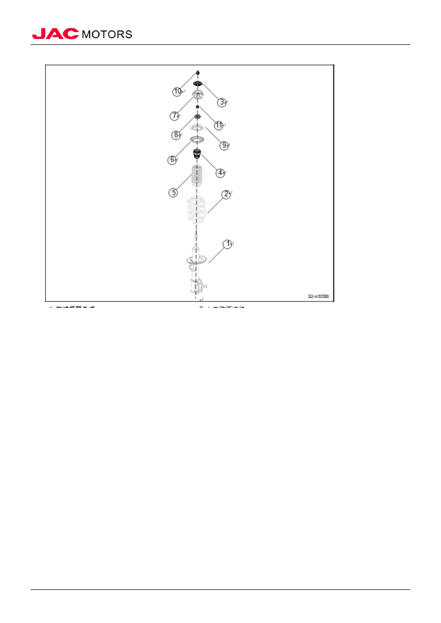
Front shock absorbers and coil springs support assembly structure 


1. Front shock absorber assembly 
2. The front coil spring 
3. The decorative cover 
4. The buffer block 
5. Dust cover 
6. Upper spring cushion 
7. Upper installation buffer block 
8. Damper bearing 
9. Upper spring seat 
10. Self-locking nuts 
11. (Fixed bearing) Nuts 


-------------------------------------------------------------------------------------------------------------------------------------------------------------


Front suspension


Front suspension  


            55 

 Sub-frame assembly structure 


1. Sub-frame assembly 
2. Hex flange locking bolt pad assembly 
3. Hex flange locking bolt pad assembly 
4. Hex flange locking bolt pad assembly 


-------------------------------------------------------------------------------------------------------------------------------------------------------------


Front suspension


Front suspension  


            56 

Front hub assembly structure 


1. Knuckle 
2. Fender 
3. Clamp 
4. Flange plate 
5. Bearing 

6. (Fixed fender) bolt 


-------------------------------------------------------------------------------------------------------------------------------------------------------------


Front suspension


Front suspension  


            57 


 (II) Technical parameters 

Item 

parameters and specifications 

Front suspension mode 

McPherson independent front suspension form with coil 
spring suspension 


Shock 
absorber 

model 

Bidirectional hydraulic cylinder 

stroke 

140mm 

Damping force 

pill 

806N±125N (0.3m/s) 

press 

443N±91N (0.3m/s) 

Coil spring 

free height:326mm 

(reference) 

Color rematk: yellow 
and white stripe 

Wheel 

alignm
ent (no 
load) 

Wheel toe 

3.75′±6.75′ 

Wheel camber 

24′±30′ 

Kingpin inclination 

10.5°±1° 

Kingpin caster 

3.65°±0.75° 

Kingpin offset 

-3.8mm 

(III) Torque parameters 

No 

Item 

Torque(N·m) 

R
e
m
a
r

1  front stabilizer bar mounting bracket and the sub-frame fixing bolts 

60~72 


2  front shock absorber and body assembly nut 

60~72 


3  front shock absorber self-locking nut 

50~70 


4  front shock absorber and steering knuckle connecting bolt 

100~1
20 


5  stabilizer link assembly and stabilizer bar / damper assembly 

connecting nut 

60~72 


6  lower arm ball pin and  lower arm connecting nut 

60~70 


7  lower arm front liner and sub frame connecting bolt 

130~1
50 


8  lower arm rear liner and sub frame connecting bolt 

130~1
50 


9  Engine rear suspension and front sub frame connecting bolt 

130~1
50 


10  front sub frame front mounting nut 

110~1
30 


11  front sub frame rear mounting nut 

60~72 


12  drive shaft and front wheel hub assembly self-locking nut 

240~2
60 


(IV) Maintenance precaution 

1. When install suspension or rubber liner, final tightening must be carried out under the condition that 
the tire is on ground and with no-load. 
2. After finish suspension components maintenance, be sure to check wheel alignment. 
3. The oil will shorten the life of the rubber liner. Be sure to clean the spilled oil. 
4. The no-load condition is the condition that fuel, engine coolant and lubricant are normally raised, 
and spare tire, jack, hand tools and mats are in designated positions. 

-------------------------------------------------------------------------------------------------------------------------------------------------------------


Front suspension


Front suspension  


            58 

5. The locking nut should not be reused. Always use a new nut during installation. When replacing, 
before tighten the locking nut, do not wipe anti-rust oil on the locking nut. 

(V) Special tools 

No. 

Tool 

Outlook 

Description 

Japanese-style  ball 
puller


Remove ball head


Damping 

spring 

puller


Remove, install damper spring


Hub 

Installation 

Tool


Install front and rear wheel hub


II. Fault diagnosis 
 

(I) Fault diagnosis table 

No. 

Failure 
Cause 

Failure Analysis  


Solution 

Remark 

1  Heavy steering 


wheel alignment improper  


Adjust 


rotation beyond lower arm ball head 
replacement 


replace 

tire pressure too low 

charge air 

With no power to steer 

Maintain or replace 

Improper 
return 

Front wheel alignment improper  


Adjust 


Shock absorber fault 

Maintain or replace 

anti-roll bar worn or damaged  


replace 

coil spring worn or damaged 


replace


Lower arm liner worn 

replace


3  Tire worn 

abnormal 

Front wheel alignment improper  


Adjust 


Tire pressure too low or too high 

Adjust pressure 

Shock absorber fault 

Maintain or replace 

Vehicle 
deviation 

front wheel alignment improper  


adjust or replace 


Lower arm ball head connector turn 
without enough resistance 

replace 

Lower arm liner worn or loosen 

replace 


No. 

Failure 
Cause 

Failure Analysis  


Solution  

Remark 


vehicle 
unilateral 
deviation 

improper front wheel alignment  

adjust or replace 


Lower arm ball head connector turn 
without enough resistance 

Replace


Lower arm bent 

Replace


coil spring worn or damaged 

Replace


-------------------------------------------------------------------------------------------------------------------------------------------------------------


Front suspension


Front suspension  


            59 


Steering 
wheel shimmy 

improper front wheel alignment 

adjust or replace 


Lower arm ball head connector turn 
without enough resistance 

Replace


Lower arm liner loose or worn 

Replace


shock absorber fault 

maintain or replace 

Anti-roll bar worn or damaged 

Replace


coil spring worn or damaged 

replace


vehicle 
sagging  

coil spring worn or damaged 

replace


shock absorber fault 

maintain or replace 


III. Lower arm assembly 

(I) Remove 

△ Note to maintain wheel balance, before removing the 

tire, mark the relative positions of the wheel. 

1. Remove the wheels refers to the wheels 
2. Remove the lower arm assembly 

1) Remove the cotter pin and slotted nut connecting the 
lower arm and knuckle. 


2). Remove the front connection bolt between the lower 
arm assembly and front sub frame. 


3).  Disengage the lower ball pin and the joint connection 
with a special tool. 

△ Note  to avoid violent demolition. 

-------------------------------------------------------------------------------------------------------------------------------------------------------------


Front suspension


Front suspension  


            60 


4) Remove front connection bolt between the lower arm 
assembly and front sub frame. 


(II) Installation 

1. Install the lower arm assembly 

1) Place the lower arm assembly to the mounting position. 

2) Install front connection bolt between the lower arm 
assembly and front sub frame. 
Tightening Torque 130 ~ 150N • m 


3) Install rear connection bolt between the lower arm 
assembly and front sub frame. 
Tightening Torque 130 ~ 150N • m

-------------------------------------------------------------------------------------------------------------------------------------------------------------


Front suspension


Front suspension  


            61 


4). Install the cotter pin and slotted nut connecting the 
lower arm and knuckle 

Tightening torque 60 ~ 72N • m 


2. Install the wheel 

IV. Front shock absorber and coil spring support assembly 

(I) Remove 

△ Note To maintain wheel balance, before removing the 

tire, mark the relative positions of the wheel. 

1. Open the engine hatch 
2. Remove the wheels refers to the wheels 
3. Remove the front shock absorber and coil spring support assembly 

1). Remove the fixing bolt connecting the front shock 
absorber in the central of the front brake hose, disengage 
the connection between the front brake hose and the front 
shock absorber. 

2). Disengage a fixing point connecting the front wheel 
speed sensor harness and front shock absorber. 

-------------------------------------------------------------------------------------------------------------------------------------------------------------


Front suspension


Front suspension  


            62 


3). Remove a fixing nut connecting the front shock 
absorber assembly and the left damper ball lever; 
disengage the front shock absorber assembly and the left 
damper ball lever. 


4) Remove a self-locking nut connecting front shock 
absorber and coil springs support assembly nut and the 
body. 


5) Remove two bolts and nuts connecting the front shock 
absorber assembly and the front knuckle. 

-------------------------------------------------------------------------------------------------------------------------------------------------------------


Front suspension


Front suspension  


            63 


6) Remove the front shock absorber and coil spring 
support assembly from the wheel cover side. 

(II) Installation 

1. Install the front shock absorber and coil springs support assembly 

1) Place the front shock absorber and the coil spring 
support assembly to the mounting position. 

2) Install two bolts and nuts connecting the front shock 
absorber assembly and the front knuckle. 
Tightening Torque 100 ~ 120N • m 


3) Inset all a self-locking nut connecting front shock 
absorber and coil springs support assembly nut and the 
body. 
Tightening torque 60 ~ 72N • m 


-------------------------------------------------------------------------------------------------------------------------------------------------------------


Front suspension


Front suspension  


            64 

4) Install a fixing nut connecting the front shock absorber assembly and the left ball pin lever. 

Tightening torque 55 ~ 65N • m 


5) Connect a fixing-point connection between the front 
wheel speed sensor harness and front shock absorber. 

6) Install the fixing bolt connecting the central of the front 
brake hose and the front shock absorber. 
Tightening torque 55 ~ 65N • m 


2. Install the wheel 
3. Close the engine hatch 

V.  Stabilizer bar 

(I) Remove 

△ Note To maintain wheel balance, before removing the 

tire, mark the relative positions of the wheel. 

1. Remove the left front wheel refers to the wheel 
2. Remove the right front wheel refers to the wheel 
3. Remove the stabilizer bar on the front sub frame and steering gear assembly refers to the front sub 
frame assembly 
4. Remove the stabilizer bar 

1). Disassemble the four hex flanges bolt pad connecting 
stabilizer bar and front sub frame. 

2) Remove the stabilizer bar fixing bracket. 

3) Remove the stabilizer bar liner. 

4) Remove the stabilizer bar. 

-------------------------------------------------------------------------------------------------------------------------------------------------------------


Front suspension


Front suspension  


            65 


(II) Installation 

1. Install the stabilizer bar 

1) Place the stabilizer bar to the front sub frame mounting 
position. 

2) Place the stabilizer bar liner, stabilizer bar mounting 
bracket; tighten the four hex flanges bolt pad connecting 
stabilizer bar and front sub frame. 
Tightening torque 60 ~ 72N • m 


2. Install the stabilizer bar of the front sub frame and steering gear assembly 
3. Install the left front wheel 
4. Install the right front wheel 

VI. Left ball pin rod assembly 

(I) Remove 

1. Lift vehicle 
2. Remove the left ball pin rod assembly 

1). Remove a self-locking nut connecting the left ball pin 
rod assembly and stabilizer bar; disengage the left ball pin 
rod assembly and stabilizer bar connection. 

-------------------------------------------------------------------------------------------------------------------------------------------------------------


Front suspension


Front suspension  


            66 


2).  Remove a self-locking nut connecting the left ball pin 
rod assembly and the front shock absorber assembly; 
disengage the left ball pin rod assembly and the front 
shock absorber connection. 


3) Remove the left ball pin rod assembly 

(II) Installation 

1. Install the left ball pin rod assembly 

1) Install a self-locking nut connecting the left ball pin rod 
assembly and front shock absorber assembly. 
Tightening torque 55 ~ 65N • m 

△ Note  self-locking nut cannot be reused, it must be 

replaced with  new ones.


2) Install a self-locking nut connecting the left ball pin rod 

-------------------------------------------------------------------------------------------------------------------------------------------------------------


Front suspension


Front suspension  


            67 

assembly and stabilizer bar. 
Tightening torque 55 ~ 65N • m 

△ Note self-locking nuts cannot be reused, it must be 

replaced with  new ones. 


2. Lower the vehicle 

VII. Front sub frame assembly 

(I) Remove 

1. Remove the left front wheel refers to the wheel 
2. Remove the right front wheel refers to the wheel 
3. Remove the left lower arm assembly refers to the lower arm assembly 
4. Remove the right lower arm assembly refers to the lower arm assembly 
5. Remove the rear suspension assembly refers to the rear suspension assembly 
6. Remove the stabilizer bar of the front sub frame and diverter assembly 

1). Remove a mounting bolt connecting the steering shaft 
with a universal joint assembly and diverter. 


2) Remove a self-locking nut connecting the left ball pin 
rod assembly and stabilizer bar. 

-------------------------------------------------------------------------------------------------------------------------------------------------------------


Front suspension


Front suspension  


            68 


3) Remove a cotter pin and slotted nut connecting the 
knuckle and tie rod. 


4). Remove the two fixing bolts connecting the front sub 
frame and the body front point. 

5) Remove the two fixing bolts connecting the front sub 
frame and the body middle point. 

6) Remove the two fixing bolts connecting the front sub 
frame and the body rear point. 

7) Remove the front sub frame with stabilizer bar and 
diverter assembly. 

7. Remove the front sub frame 

1). Remove the two hex flange bolts connecting diverter 
assembly and the front sub frame and two locking nuts on 
the diverter. 


2) Remove the diverter assembly. 

-------------------------------------------------------------------------------------------------------------------------------------------------------------


Front suspension


Front suspension  


            69 


3). Disassemble four hex flange bolts pad connecting 
stabilizer bar and front sub frame. 

4) Remove the stabilizer bar fixing bracket. 

5) Remove the stabilizer bar liner. 

6) Remove the stabilizer bar. 


(II) Installation 

1. Install the front sub frame 

1) Place the stabilizer bar to the mounting position of the 
front sub frame. 

2) Place the stabilizer bar liners, stabilizer bar mounting 
bracket; tighten the four hex flange bolts pad connecting 
the stabilizer bar and front sub frame. 
Tightening torque 60 ~ 72N • m 


3) Place the diverter assembly to the front sub frame 
mounting position. 

4) Install the two hex flange bolts connecting diverter 
assembly and the front sub frame and two locking nuts of 
diverter. 
Tightening torque 95 ~ 105N • m

-------------------------------------------------------------------------------------------------------------------------------------------------------------


Content      ..     3      4      5      6     ..