JAC S2. Service Manual - part 13


  Index      JAC     JAC S2. Service Manual


Search            copyright infringement  


Content      ..     11      12      13      14     ..


JAC S2. Service Manual - part 13


Seat and Safety Belt


Seat and Safety Belt                                                                                                                                                                                      181 


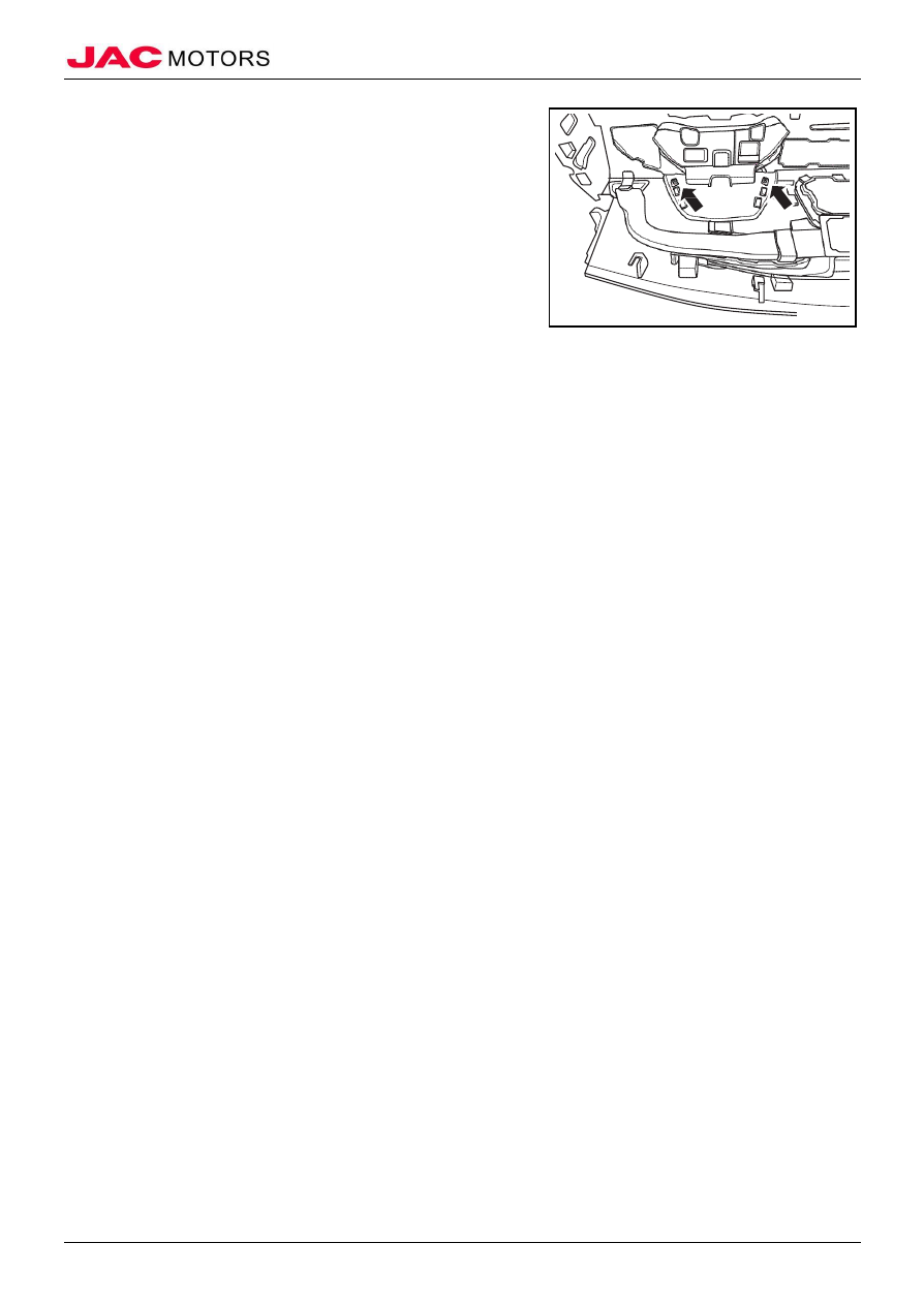
2). Tighten 2 fixed bolts connecting combination meter cover 

assembly and dashboard assembly; 


2.  Install combination meter assembly 

3.  Install central left side trim panel assembly 

4.  Install lower guard panel assembly of driver's side 

5.  Install end cover of dashboard (left) 

6.  Install central right side trim panel assembly 

7.  Connect battery negative electrode 

8.  Close engine compartment cover 


-------------------------------------------------------------------------------------------------------------------------------------------------------------

                                                                                                        Dashboard


Dashboard                                                                                                                                                                                                      182 


Dashboard 


I、Summary 


(I)Structure Overview 


Dashboard Exposed Diagram 


1. Dashboard assembly 

2. Left end cover of dashboard 

3. Right end cover of dashboard 

4. Lower guard panel assembly of driver’s side 

5. Indoor electrical box cover 

6. Combination meter cover assembly 

7. Upper jacketing of steering column 

8. Lower jacketing of steering column 

9. Central right side trim panel assembly 

10. Central left side trim panel assembly 

11. Decoration panel 

12. Radio panel assembly 

13. Glove box assembly 

14. Exterior cover plate of glove box 

15. Glove box lock assembly 

16. Central cover plate assembly 


(II)Torque Parameter 


No.


Item


Torque 

(N·m)


Fixed bolt of lower guard panel of driver’s side 

1.4 

Fixed bolt of radio panel 

1.4 

Fixed bolt of front part of auxiliary dashboard 

1.4 

Fixed bolt of rear part and left/right side of auxiliary dashboard 

5~7 

Fixed nut of dashboard assembly 

5~7 

-------------------------------------------------------------------------------------------------------------------------------------------------------------

                                                                                                        Dashboard


Dashboard                                                                                                                                                                                                      183 

No.


Item


Torque 

(N·m)


Fixed bolt of dashboard assembly 

5~7 

Fixed nut of A/C main host and beam 

5~7 

Fixed bolt of beam 

20 

Fixed bolt of beam and front wall 

20 


(III)Maintenance Note 


(1). Please observe the handling directions of airbag system strictly, or vehicle damage and personal injury may be caused. 
(2). Please dismantle the negative electrode of battery and keep waiting for at least one minutes before removing electric connections, 
otherwise damage to the vehicle will be caused. 
(3). Please protect the parts with cloth to prevent damage when dismantling and installing the components. 
(4). Please wrap the flat-blade of screwdriver with cloth when removing the metal clamp from the trimming 
(5). Please guard against damage of the body parts. 
(6). Make sure the clamps are fixed into plate hole of the vehicle body securely when installing body trim, and then carefully push 
them in. 
(7). Two people are needed when a person cannot complete the work of dismantling and installing some components in order to 
avoid falling. 
(8).Avoid overexertion when dismantling and installing some trims, which may cause deformation of parts. 

-------------------------------------------------------------------------------------------------------------------------------------------------------------

                                                                                                        Dashboard


Dashboard                                                                                                                                                                                                      184 


II、Auxiliary Dashboard Assembly 


(I)Removal 


1.  Open engine compartment cover 

2.  Disconnect battery negative electrode 

3.  Remove front extension plate assembly 

1). Remove 2 expansion buckles in both left and right extension 

plate; 

2). Disconnect connection of extension plate and auxiliary 

dashboard assembly, and take down extension plate; 


4.  Remove saucer cover plate assembly 

1). Pry saucer cover plate assembly in rear part of auxiliary 

dashboard; 


5.  Remove front storage box assembly 

1). Pry storage box assembly in front part of auxiliary 

dashboard; 


2). Disconnect wiring harness connector; 

3). Take down front storage box assembly; 


-------------------------------------------------------------------------------------------------------------------------------------------------------------

                                                                                                        Dashboard


Dashboard                                                                                                                                                                                                      185 

6.  Remove auxiliary dashboard assembly 

1).  Remove fixed bolt below lower saucer cover plate; 


2).  Remove fixed bolt below front storage box assembly; 


3). Disconnect connection of transmission operation panel and 

auxiliary dashboard; 


4). Remove fixed bolt 

①  in both sides of front part of 

auxiliary dashboard and fixed bolt 

②  in both sides of 

middle part of auxiliary dashboard; 


-------------------------------------------------------------------------------------------------------------------------------------------------------------

                                                                                                        Dashboard


Dashboard                                                                                                                                                                                                      186 


5). Pull manual brake rod to maximum angle, and take down 

auxiliary dashboard assembly; 


(II)Installation 


1.  Install auxiliary dashboard assembly 

1).  Pull manual brake rod to maximum angle, and place 

auxiliary dashboard assembly to installation position; 


2). Tighten fixed bolt 

①  in both sides of front part of auxiliary 

dashboard ; 

Tighten torque 

1.4N·m 

3). Tighten fixed bolt 

②  in both sides of middle part of 

auxiliary dashboard; 

Tighten torque 

5~7N·m 


4). Connect connection of transmission operation panel and 

auxiliary dashboard; 


-------------------------------------------------------------------------------------------------------------------------------------------------------------

                                                                                                        Dashboard


Dashboard                                                                                                                                                                                                      187 


5). Tighten fixed bolt below front storage box assembly; 

Tighten torque 

1.4N·m 


6). Tighten fixed bolt below saucer cover plate; 

Tighten torque 

5~7N·m 


2.  Install front storage box assembly 

1). Connect storage box wiring harness, place storage box to 

installation position and tighten buckles; 


3. Install saucer cover plate assembly 

1). Place saucer cover plate to installation position and tighten 

buckles; 


-------------------------------------------------------------------------------------------------------------------------------------------------------------

                                                                                                        Dashboard


Dashboard                                                                                                                                                                                                      188 


4.  Install front extension plate assembly 

1). Place front extension plate to installation position; 

2). Tighten 2 expansion buckles in both sides of left and right 

extension plate; 


5.  Connect battery negative electrode 

6.  Close engine compartment cover 

-------------------------------------------------------------------------------------------------------------------------------------------------------------

                                                                                                        Dashboard


Dashboard                                                                                                                                                                                                      189 


III、Central Right Side Trim Panel Assembly 


(I)Removal 


1.  Open engine compartment cover 

2.  Disconnect battery negative electrode 

3.  Remove central right side trim panel assembly 

1). Pry buckles connecting central right side trim panel 

assembly and dashboard assembly; 


2). Disconnect wiring harness connector, and take down central 

right side trim panel assembly; 


(II)Installation 


1.  Install central right side trim panel assembly 

1). Connect wiring harness connector; 

2). Place central right side trim panel assembly to installation, 

and tighten buckles; 


2.  Connect battery negative electrode 

3.  Close engine compartment cover 

-------------------------------------------------------------------------------------------------------------------------------------------------------------

                                                                                                        Dashboard


Dashboard                                                                                                                                                                                                      190 


IV、Central Right Side Trim Panel Assembly 


(I)Removal 


1.  Open engine compartment cover 

2.  Disconnect battery negative electrode 

3.  Remove central right side trim panel assembly    Refer to "Remove central right side trim panel assembly" 

4.  Remove central right side trim panel assembly 

1).  Remove 4 fixed bolts of central right side trim panel 

assembly and right side air outlet port assembly; 

2). Take down right side air outlet port assembly; 


3). Remove 6 fixed bolts of central right side trim panel 

assembly and central air outlet port assembly; 


4). Pry buckles connecting central right side trim panel 

assembly and central air outlet port assembly; 

5). Take down central right side trim panel assembly; 


(II)Installation 


1.  Install central right side trim panel assembly 

1). Connect buckles connecting central right side trim panel 

assembly and central air outlet port assembly; 

2). Tighten 6 fixed bolts of central right side trim panel 

assembly and central air outlet port assembly; 


-------------------------------------------------------------------------------------------------------------------------------------------------------------

                                                                                                        Dashboard


Dashboard                                                                                                                                                                                                      191 


3). Connect buckles connecting central right side trim panel 

assembly and right side air outlet port assembly; 

4). Tighten 4 fixed bolts of central right side trim panel 

assembly and right side air outlet port assembly; 


2.  Install central right side trim panel assembly 

3.  Connect battery negative electrode 

4.  Close engine compartment cover 

-------------------------------------------------------------------------------------------------------------------------------------------------------------

                                                                                                        Dashboard


Dashboard                                                                                                                                                                                                      192 


V、Radio Panel Assembly 


(I)Removal 


1.  Open engine compartment cover 

2.  Disconnect battery negative electrode 

3.  Remove central right side trim panel assembly    Refer to "Central right side trim panel assembly" 

4.  Remove radio panel assembly 

1). Remove fixed bolt in left/right side of radio panel; 

2). Pry buckles of radio panel assembly and dashboard 

assembly, and take down radio panel assembly; 


(II)Installation 


1.  Install radio panel assembly 

1). Place radio panel assembly to installation position and 

tighten buckles; 

2). Tighten fixed bolts in left and right side of radio panel 

assembly; 

Tighten torque 

1.4N·m 


2.  Install central right side trim panel assembly 

3.  Connect battery negative electrode 

4.  Close engine compartment cover 

-------------------------------------------------------------------------------------------------------------------------------------------------------------

                                                                                                        Dashboard


Dashboard                                                                                                                                                                                                      193 


VI、Lower Guard Panel Assembly of Driver's Side 


(I)Removal 


1.  Open engine compartment cover 

2.  Disconnect battery negative electrode 

3.  Remove end cover of dashboard (left)  Refer to ""end cover of dashboard 

4.  Remove lower guard panel assembly of driver's side 

1). Remove left side 2 fixed bolts of lower guard panel 

assembly of driver's side; 


2). Remove lower part fixed bolt of right side of lower guard 

panel assembly of driver's side; 


3). Pry buckles connecting lower guard panel assembly of 

driver's side and dashboard assembly; 

4). In order from left to right, disconnect wiring harness 

connector of headlight regulating switch, rearview mirror 

regulating switch, light regulating switch, ESP switch; 


5). Disconnect connection of OBD diagnosis wiring harness 

and lower guard panel of driver’s side; 

6). Take down lower guard panel assembly of driver's side

。 


-------------------------------------------------------------------------------------------------------------------------------------------------------------

                                                                                                        Dashboard


Dashboard                                                                                                                                                                                                      194 


(II)Installation 


1.  Install lower guard panel assembly of driver's side 

1). Connect connection of OBD diagnosis wiring harness and 

lower guard panel of driver’s side; 


2). In order from left to right, connect wiring harness connector 

of headlight regulating switch, rearview mirror regulating 

switch, light regulating switch, ESP switch; 


3). Place lower guard panel of driver’s side to installation 

position, and tighten buckles connecting dashboard; 

4). Tighten 2 fixed bolts of left side of lower guard panel of 

driver’s side; 

    Tighten torque 

1.4N·m 


5). Tighten lower part fixed bolt of right side of lower guard 

panel assembly of driver's side; 

    Tighten torque 

1.4N·m 


2.  Install end cover of dashboard (left) 

3.  Connect battery negative electrode 

4.  Close engine compartment cover 

-------------------------------------------------------------------------------------------------------------------------------------------------------------

                                                                                                        Dashboard


Dashboard                                                                                                                                                                                                      195 


VII、Central Left Side Trim Panel Assembly 

(I)Removal 


1.  Open engine compartment cover 

2.  Disconnect battery negative electrode 

3.  Remove central right side trim panel assembly    Refer to "Central right side trim panel assembly" 

4.  Remove end cover of dashboard (left)  Refer to "End cover of dashboard" 

5.  Remove lower guard panel assembly of driver's side    Refer to "Lower guard panel assembly of driver's side" 

6.  Remove central left side trim panel assembly 

1). Remove fixed bolt of central left side trim panel assembly 

and dashboard assembly; 

2). Pry buckles connecting central left side trim panel assembly 

and dashboard assembly, and take down trim panel 

assembly; 


(II)Installation 


1.  Install central left side trim panel assembly 

1). Place central left side trim panel assembly to installation 

position, and tighten buckles; 

2). Tighten fixed bolt of trim panel and dashboard assembly; 

Tighten torque 

1.4N·m 


2.  Installlower guard panel assembly of driver's side 

3.  Installend cover of dashboard (left) 

4.  Installcentral right side trim panel assembly 

5.  Connect battery negative electrode 

6.  Close engine compartment cover 

-------------------------------------------------------------------------------------------------------------------------------------------------------------

                                                                                                        Dashboard


Dashboard                                                                                                                                                                                                      196 


VIII、Glove Box Assembly 


(I)Removal 


1.  Remove glove box assembly 

1). Open glove box to maximum angle, pull side wall of glove 

box and pull out to make stop cylinder slip out; 


2). Place glove box flat, and pull glove box from opening port 

of dashboard; 


(II)Installation 


1.  Install glove box assembly 

1). Place glove box flat, make direction of rotation shaft 

opening of glove box is the same with rotation shaft of 

glove box, push glove box forward, and make rotation 

shaft of glove box into rotation shaft opening of glove 

box; 

-------------------------------------------------------------------------------------------------------------------------------------------------------------


Content      ..     11      12      13      14     ..