Isuzu Trooper (1998-2002 year). Manual - part 563


  Index      Isuzu     Isuzu Trooper - service repair manual 1998-2002 year


Search            


Content   ..  561  562  563  564   ..


Isuzu Trooper (1998-2002 year). Manual - part 563


6A – 60 ENGINE MECHANICAL

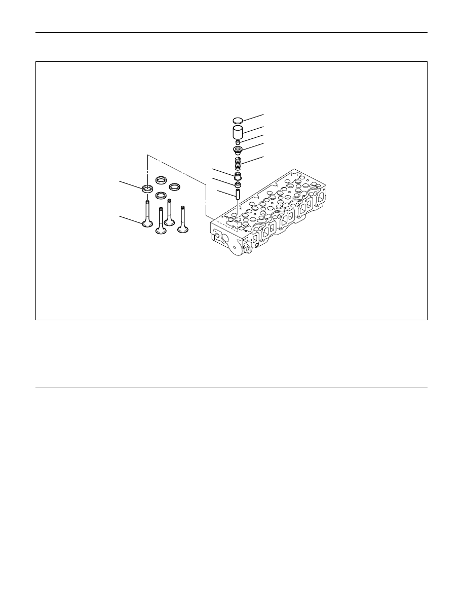
VALVE STEM SEAL, VALVE SPRING AND ADJUSTER

REMOVAL

1. Disconnect battery ground cable.
2. Drain engine coolant.
3. Remove the air duct from between air cleaner and

turbocharger.

4. Remove intercooler assembly.

Refer to “Intercooler” in this manual.

5. Remove oil level gauge guide assembly.
6. Disconnect PCV hose.
7. Disconnect EGR vacuum hose.
8. Disconnect harness connectors around the cylinder

head such as the injector, CMP sensor, MAP
sensor, EGR sensor, EVRV, IAT sensor, A/C
compressor, TP stepping motor, TP sensor and fuel
temperature sensor etc.

9. Remove A/C compressor assembly.

10. Remove A/C compressor bracket.
11. Remove generator assembly and take out drive

belt.

12. Remove heat protector, remove exhaust valve

assembly.

13. Remove water cooling hose and lubrication pipe for

turbocharger.

14. Remove turbocharger assembly.
15. Remove hose between thermostat and radiator.
16. Remove noise insulator cover of cylinder head.

NOTE: Do not damage injector harness.

17. Remove high pressure oil pipe.
18. Remove timing belt cover.
19. Remove CMP sensor bracket.
20. Remove timing belt tensioner then remove timing

belt.

21. Remove camshaft pulley.
22. Remove front plate.
23. Remove engine coolant pipe between cylinder

head and water pump.

1

2
3
4

5

6

9

10

7

8

011RW031

Legend

(1)

Adjuster

(2)

Tappet

(3)

Split Collar

(4)

Spring Seat Upper

(5)

Valve Spring

(6)

Spring Seat Lower

(7)

Valve Stem Seal

(8)

Valve Guide

(9)

Valve Seat

(10)

Valve

ENGINE MECHANICAL 6A – 61

24. Remove fuel pipe between fuel pump and intake

manifold.

25. Remove fuel return pipe from rear of cylinder head.
26. Remove intake manifold assembly.
27. Disconnect glow plug harness and remove glow

plug.

28. Remove cylinder head cover.
29. Remove injector harness connector.
30. Disconnect harness connector from oil pressure

sensor and oil temperature sensor on the oil rail.

31. Remove injector harness assembly.
32. Remove injector clamp.
33. Remove injector is fixed bolts.
34. Remove injector assembly.
35. Remove oil rail.
36. Remove camshaft carrier assembly with camshaft.
37. Remove cylinder head assembly.
38. Disassemble valve spring according to the following

method.
1) Use valve spring compressor then remove split

collars.

2) Valve spring compressor: 5-8840-2441-0

NOTE: Put removed valve spring in order of cylinder
number.

39. Valve stem seal.

1) Use a screwdriver or pliers to remove valve

stem seal.

NOTE: Do not reuse removed valve stem seal.

INSPECTION AND REPAIR

Make the necessary adjustments, repairs and part
replacements if excessive wear or damage is
discovered during inspection.

Valve spring

CAUTION: Visually inspect the valve springs and
replace them if damage or abnormal wear is
evident.

1. Free height

1) Measure the free height of the springs. The

springs must be replaced if the height is below
the specified limit.

Standard: 45.85 mm (1.8051in)
Limit: 43.9 mm (1.7283 in)

2. Squareness

1) Measure the valve spring squareness with a

steel square.

2) Replace the valve springs if the measured value

exceeds the specified limit.

Limit: 1.6 mm (0.063 in)

014rw042

014rs004

014rs005

6A – 62 ENGINE MECHANICAL

3. Spring tension

1) Use a spring tester to compress the springs to

the installed height. Measure the compressed
spring tension.

2) Replace the springs if the measured tension is

below the specified limit.

Standard: 236.0 N (24 kg/53 lb)
Limit: 205.0 N (21 kg/46 lb)

Valve Guide

CAUTION: Taking care not to damage the valve seat
contact surface, when removing carbon adhering to
the valve head.
Carefully inspect the valve stem for scratching or
abnormal wear. If these conditions are present, the
valve and the valve guide must be replaced as a set.

1. Valve Guide Clearance

1) Measure the valve stem diameter with a

micrometer.
If the valve stem diameter is less than the
specified limit, the valve and the valve guide
must be replaced as a set.

Diameter of Valve stem:Inlet

Standard: 6.959 – 6.977 mm (0.2740 – 0.2747 in)
Limit: 6.92 mm (0.2724 in)

Diameter of Valve stem:Exhaust

Standard: 6.952 – 6.97 mm (0.2737 – 0.2744 in)
Limit: 6.90 mm (0.2717 in)

2) Measure the inside diameter of the valve guide

with a micrometer.

3) Subtract the measured outer diameter of the

valve stem from the measured inner diameter of
the valve guide.
If the valve exceeds the specified limit, the valve
and the valve guide must be replaced as a set.

Inlet clearance

Standard: 0.023 – 0.053 mm (0.0009 – 0.0021 in)
Limit: 0.19 mm (0.0075 in)

Exhaust clearance

Standard: 0.03 – 0.063 mm (0.0012 – 0.0025 in)
Limit: 0.20 mm (0.0079 in)

014RS006

014RS007

ENGINE MECHANICAL 6A – 63

Valve Guide Replacement

1. Using the special tool, drive out the valve guide

from the combustion chamber side.
Valve guide replacer: 9-8523-1212-0

2. Apply engine oil to the outside of the valve guide.

Using the special tool, drive in a new valve guide
from cylinder head upper face side, and check the
valve guide height.
Valve guide replacer: 9-8523-1212-0

Height: 8.0 mm (0.315 in)

NOTE: If the valve guide has been removed, both the
valve and the valve guide must be replaced as a set.

Valve Thickness

1. Measure the valve thickness.
2. If the measured value is less than the specified

limit, the valve and the valve guide must be
replaced as a set.

Inlet

Standard: 1.2 mm (0.0472 in)
Limit: 1.1 mm (0.0433 in)

Exhaust

Standard: 1.2 mm (0.0472 in)
Limit: 1.1 mm (0.0433 in)

Contact surface angle on valve seat on
valve

1. Measure contact surface angle on valve seat.

2. If the measured value exceeds the limit, replace

valve, valve guide and valve seat as a set.

Standard: 68°

011RW001

012RW052

012RW060

014RW018


Content   ..  561  562  563  564   ..