Isuzu Trooper (1998-2002 year). Manual - part 562


  Index      Isuzu     Isuzu Trooper - service repair manual 1998-2002 year


Search            


Content   ..  560  561  562  563   ..


Isuzu Trooper (1998-2002 year). Manual - part 562


6A – 56 ENGINE MECHANICAL
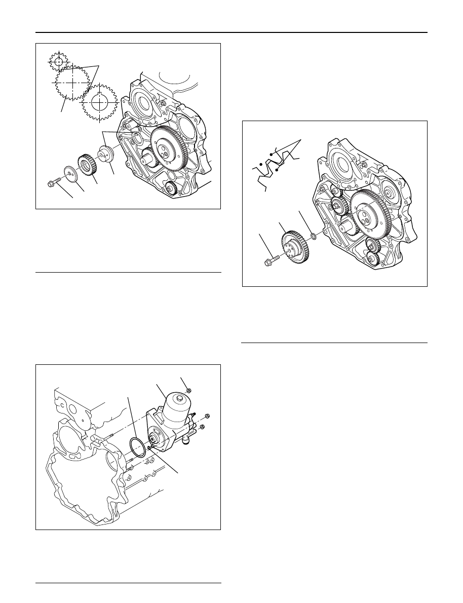
Legend

(1) Bolt
(2) Retainer
(3) Idle Gear B
(4) Idle Gear B Shaft
(5) Align Mark

6. High pressure oil pump

1) Install O-ring on the high pressure oil pump.
2) Install the high pressure oil pump to the timing

gear case, tighten the nut to the specified
torque. Apply Loctite No. 262 to the stud bolts.

Torque: 20 N·m (2.0 kg·m/14 lb ft)

NOTE: Be sure to set O-ring completely.

Legend

(1) O-ring (large)
(2) High pressure oil pump
(3) Nut
(4) O-ring (small)

7. High pressure oil pump

1) Install O-ring on the oil pump shaft with grease

and install the gear with the idle gear A timing
mark set at the oil pump gear timing mark.

2) Tighten center bolt to the specified torque.

Torque: 75 N·m (7.6 kg·m / 55 lb ft)

NOTE: Be sure to align timing marks with each other.

Legend

(1) O-ring
(2) High Pressure Oil Pump Gear
(3) Center Bolt
(4) Timing Mark

8. Remove lock from idle gear.

1) Remove lock bolt from idle gear A and remove

lock pin from idle gear C.

9. Timing gear case assembly

1) Clean fixing surface of timing gear case.
2) Install the gasket on the idle gear rear side end.
3) Apply liquid gasket (TB1207C or equivalent) to

the timing gear case fitting surface.

NOTE: Be sure to apply liquid gasket evenly.

4) Install timing gear case and tighten bolts to the

specified torque.

Torque: 20 N·m (2.0 kg·m / 14 lb ft)

NOTE: Must install within 5 minutes after applying liquid
gasket.

3

5

5

4

3

2

1

014R200008

1

2

4

3

040RW007

4

GEAR:O/PUMP

IDLE GEAR A

1

2

3

040RW005

ENGINE MECHANICAL 6A – 57

10. Vacuum pump

1) Install vacuum pump and tighten bolts to

specified torque.

Torque: 25 N·m (2.5 kg·m / 18 lb ft)

2) Install noise insulator cover.

11. Power steering pump (P/S)

1) Install P/S pump.

Torque: 22 N·m (2.2 kg·m / 16 lb ft)

12. Install front plate.

Torque: 20 N·m (2.0 kg·m / 14 lb ft)

13. High pressure oil pump pulley.

1) Install oil pump pulley and tighten to specified

torque.

Torque:10 N·m (1.0 kg·m / 87 lb in)

2

2~2.5mm

2~2.5mm

Apply liquid gasket around inside 
of the bolt hole

Bolt hole

Inside

Outside

F06HX00001

052RW001

430RW017

012RW035

6A – 58 ENGINE MECHANICAL

14. Camshaft pulley

1) Align TDC mark with crankshaft pulley and gear

case cover.

2) Set camshaft stopper on the end of intake and

exhaust camshaft.

Camshaft Stopper: 5-8840-2592-0

3) Install key to camshaft and install camshaft

pulley.

4) Apply engine oil to camshaft pulley fixing bolt

and tighten bolt with angular tightening method.

First step: 40 N·m (4.1 kg·m / 30 lb ft)
Second step: 60° to 90°

15. Timing belt

1) Install tensioner and tighten the bolt temporarily.
2) Align timing mark with camshaft pulley timing

mark and timing gear case timing mark.

3) Set No.1 cylinder TDC position.

4) Install the timing belt in the following order

camshaft pulley, oil pump pulley, tensioner.

NOTE: 

1) It is recommended for easy installation that the belt

be secured with a double clip after it is installed to
each pulley.

2) The “ISUZU” mark should be read from the front of

the engine when installing the timing belt.

5) Install the belt tensioner.
6) Conform not phase difference each pulley.
7) Tension the timing belt with two turns of the

crankshaft.

8) Tighten the tensioner bolt in order A to B to the

specified torque.

Torque: Bolt A 50 N·m (5.1 kg·m/37 lb ft)

Bolt B 20 N·m (2.0 kg·m/14 lb ft)

Legend

(1) Align Mark
(2) Camshaft Pulley
(3) Timing Belt
(4) Oil Pump Pulley
(5) Tension Bolt B
(6) Tensioner Assy
(7) Tensioner Bolt A
(8) Tensioner Spring

16. CMP sensor bracket

1) Install CMP sensor bracket and tighten bolt to

the specified torque.

Torque: 20 N·m (2.0 kg·m / 14 lb ft)
17. Timing belt cover

1) Install timing belt cover and tighten bolt to the

specified torque.

Torque: 9 N·m (0.9 kg·m / 78 lb in)

2) Tighten CMP sensor to the specified torque.

Torque: 9 N·m (0.9 kg·m / 78 lb in)

012RW036

012RW099

1

2

3

8

6

7

4

5

F06R200006

ENGINE MECHANICAL 6A – 59

18. Crankshaft damper pulley

1) Insert damper pulley with the crankshaft key

groove set on the key.

2) Tighten damper pulley bolt to the specified

torque. 

Torque: 216 N·m (22 kg·m / 159 lb ft)

19. Cooling fan Assembly

1) Install the cooling fan assembly to the fan pulley,

tighten the nuts to the specified torque.

Torque: 8 N·m (0.8 kg·m / 69 lb in)
20. AC generator drive belt.

1) Temporarily tighten generator fixing bolts and

belt tensioner adjustment plate.

2) Tension the generator drive belt then tighten the

generator fixing bolt.

Torque: 40 N·m (4.1 kg·m / 30 lb ft)

3) Tighten the belt tensioner adjustment plate bolt.

Torque: 20 N·m (2.0 kg·m / 14 lb ft)

012RW039

014RW163

012RW032


Content   ..  560  561  562  563   ..