Isuzu Trooper (1998-2002 year). Manual - part 561


  Index      Isuzu     Isuzu Trooper - service repair manual 1998-2002 year


Search            


Content   ..  559  560  561  562   ..


Isuzu Trooper (1998-2002 year). Manual - part 561


6A – 52 ENGINE MECHANICAL

TIMING GEAR 

REMOVAL

1. Loosen fixing bolt for generator and remove

generator assembly.

2. Remove fixing nuts, then remove cooling fan

assembly and fan pulley.

3. Remove crankshaft damper pulley.
4. Belt cover

1) Disconnect harness connector of CMP

(camshaft position) sensor.

2) Remove CMP sensor.
3) Remove belt cover.

5. Loosen belt tensioner to remove timing belt.
6. Remove camshaft pulley.
7. Remove high pressure oil pump pulley.
8. Remove front plate.
9. Remove vacuum pump.

10. Remove power steering pump.
11. Remove timing gear case cover assembly.
12. Idle gear A.

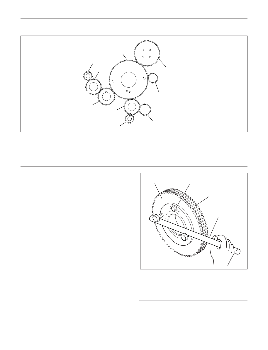
1) Set two bolts to sub gear of idle gear A and turn

it to align the tooth of idle gear A then lock them
by bolt as show in the illustration.

2) Remove idle gear A fixing bolts.
3) Remove idle gear A.

Legend

(1) Sub-Gear
(2) Main Gear
(3) Bar
(4) Locking Bolt

2

3

4

5

8

7

6

9

1

020RW028

Legend

(1)

Idle Gear A

(2)

High Pressure Oil Pump Gear

(3)

Vacuum Pump Gear

(4)

Power Steering Pump Gear

(5)

Balance Gear LH

(6)

Idle Gear C

(7)

Crankshaft Gear

(8)

Balance Gear RH

(9)

Idle Gear B

4

1

2

3

014RW177

ENGINE MECHANICAL 6A – 53

Legend

(1) Bolt
(2) Retainer
(3) Idle Gear A
(4) Idle Gear A Shaft
(5) Align Mark
(6) Crankshaft Gear
(7) O-Ring

13. Idle gear C

1) Use the special tool on idle gear C, turning the

sub gear to align the teeth, then set lock pin.

2) Remove idle gear C fixing bolt then remove the

idle gear C with flange.

Camshaft Gear Tool : 5-8840-2591-0

Legend

(1) Lock pin
(2) Camshaft Gear Tool

Legend

(1) Bolt
(2) Retainer
(3) Idle Gear C
(4) Idle Gear C Shaft
(5) Align Mark
(6) Align Mark
(7) Idle Gear A
(8) Balance Shaft Gear LH
(9) Timing Mark

14. Idle gear B

1) Loosen idle gear B fixing bolt to remove idle

gear B with flange.

Legend

(1) Bolt
(2) Retainer
(3) Idle Gear B
(4) Idle Gear B Shaft
(5) Align Mark

3

6

5

4

3

2

1

7

1

7

014R200007

1

2

014RW181

1

2

3

4

5

5

6

6

8

8

3

7

7

9

9

9

014RW175

3

5

5

4

3

2

1

014R200008

6A – 54 ENGINE MECHANICAL

15. High pressure oil pump

1) Remove oil pump gear fixing bolt then remove

oil pump.

Legend

(1) O-Ring
(2) High Pressure Oil Pump Gear
(3) Bolt
(4) Timing Mark

16. Remove balance shaft gear LH. and RH.
17. Remove crankshaft gear.

INSTALLATION

1. Crankshaft gear

1) Force key into the crankshaft and insert

crankshaft gear with the crankshaft gear key
groove set on the key.

Legend

(1) Crankshaft Gear Installer
(2) Crankshaft Gear

2.

Balance shaft gear

1) Install the balance shaft gear RH to balance

shaft, tighten center bolt to the specified torque.

Torque : 32 N·m (3.3 kg·m/24 lb ft)

2) Install thrust plate for balance shaft LH before

installing the balance shaft gear LH.

Torque : 25 N·m (2.5 kg·m/18 lb ft)

3) Install balance shaft gear LH to balance shaft,

tighten center bolt to the specified torque.

Torque : 32 N·m (3.3 kg·m/24 lb ft)

Legend

(1) Center Bolt
(2) Plate
(3) Balance Shaft Gear RH
(4) Timing Mark

4

GEAR:O/PUMP

IDLE GEAR A

1

2

3

040RW005

1

2

2

012RW066

3

4

2

1

014RW173

ENGINE MECHANICAL 6A – 55

3. Idle gear A

1) Insert idle gear A shaft to align alignment mark

between idle gear A shaft and timing gear case.

2) Apply engine oil to the shaft surface.
3) Install the idle gear A to align the timing mark

with the crankshaft gear.

4) Install the flange, tighten bolts to the specified

torque.

Torque: 25 N·m (2.5 kg·m/18 lb ft)

Legend

(1) Bolt
(2) Retainer
(3) Idle Gear A
(4) Idle Gear A Shaft
(5) Align Mark
(6) Crankshaft Gear
(7) O-Ring

NOTE: Conform not difference timing marks between
each others.

4. Idle gear C

1) Insert idle gear C shaft to align alignment mark

between idle gear C shaft and timing gear case.

2) Apply engine oil to the shaft surface.
3) Align timing mark on idle gear C with balance

shaft gear LH and idle gear A timing marks, then
insert idle gear C.

4) Set position of idle gear C flange with a dowel

pin, tighten bolt to the specified torque.

Torque: 25 N·m (2.5 kg·m/18 lb ft)

Legend

(1) Bolt
(2) Retainer
(3) Idle Gear C
(4) Idle Gear C Shaft
(5) Align Mark
(6) Align Mark
(7) Idle Gear A
(8) Balance Shaft Gear LH
(9) Timing Mark

5. Idle gear B

1) Insert idle gear B shaft to align alignment mark

between idle gear B shaft and timing gear case.

2) Apply engine oil to the shaft surface.
3) Align timing mark on idle gear B with balance

shaft gear RH and crankshaft gear timing marks,
then insert idle gear B.

4) Install flange and tighten the bolt to the specified

torque.

Torque: 51 N·m (5.2 kg·m/38 lb ft)

3

6

5

4

3

2

1

7

1

7

014R200007

1

2

3

4

5

5

6

6

8

8

3

7

7

9

9

9

014RW175


Content   ..  559  560  561  562   ..