Isuzu Trooper (1998-2002 year). Manual - part 560


  Index      Isuzu     Isuzu Trooper - service repair manual 1998-2002 year


Search            


Content   ..  558  559  560  561   ..


Isuzu Trooper (1998-2002 year). Manual - part 560


6A – 48 ENGINE MECHANICAL

DISASSEMBLY

1. Injector clamp 
2. Injector assembly
3. Oil rail assembly
4. Camshaft bracket
5. Camshaft
6. Oil seal
7. Plug

NOTE: Before starting disassembly above, drain oil
from oil rail to prevent oil from entering the cylinder.

REASSEMBLY

1. Camshaft

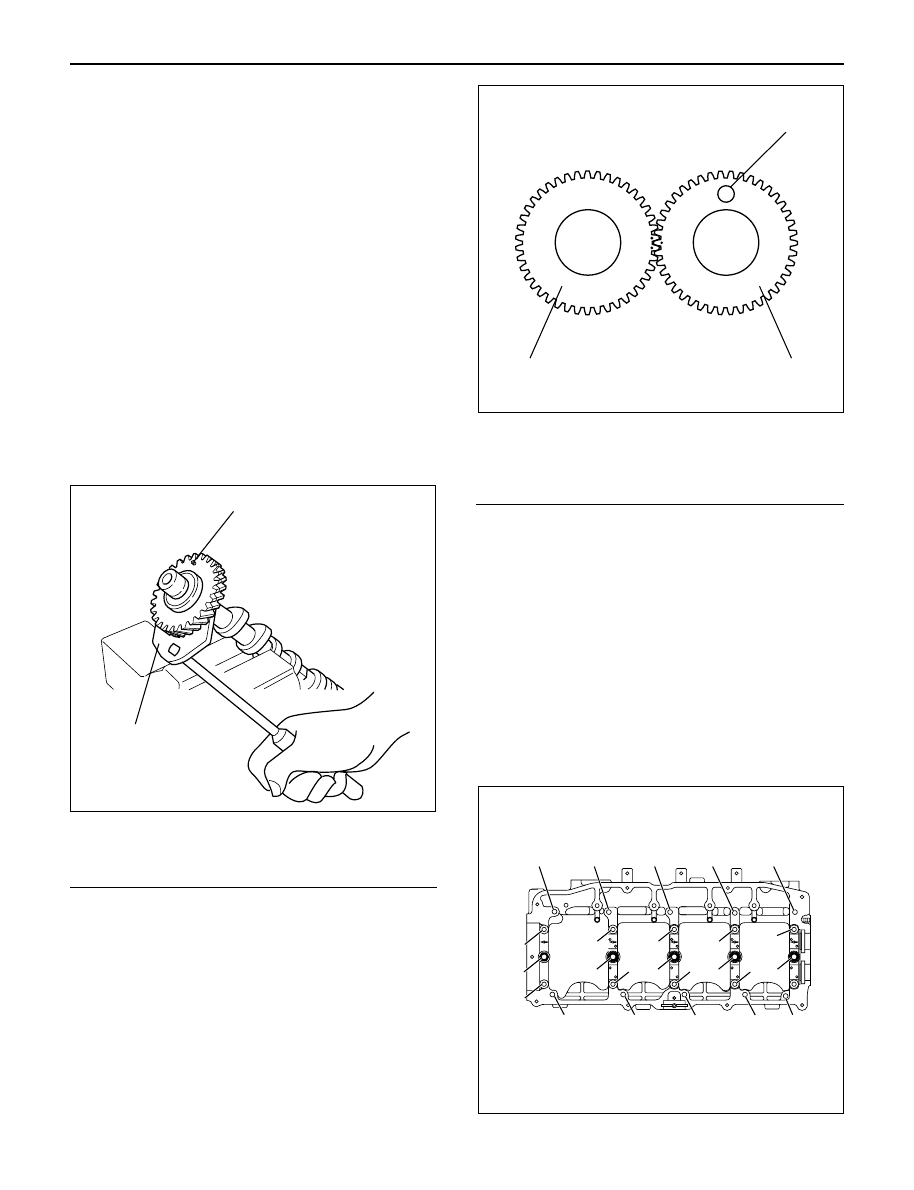
1) Before reassembling the camshaft to the

camshaft carrier, align the holes between the
main gear and the sub gear on the intake side of
the camshaft gear with a special tool.

2) Set lock pin to gear holes from sub gear side.
Camshaft Gear Tool: 5-8840-2591-0

Legend

(1) Locking pin
(2) Special tool

3) Apply engine oil to the camshaft gear tooth.
4) Apply engine oil to the journal on the camshaft

carrier.

5) Align the timing mark on the intake and exhaust

camshaft gear and put on the camshaft carrier.

Legend

(1) Locking pin
(2) Intake side camshaft gear
(3) Exhaust side camshaft gear

6) Apply liquid gasket (TB1207B or equivalent) to

No. 1 camshaft bracket matching surface.

7) Set No. 1 to No. 5 camshaft bracket on camshaft

carrier.

8) Temporarily tighten bracket bolts B and C.

Temporal Torque: 20 N·m (2.0 kg·m/14 lb ft)

9) Put gasket on the cylinder head.

10) Install camshaft carrier onto the cylinder head

and tighten bolts to specified torque.

Torque: A; 22 N·m (2.2 kg·m/16 lb ft)

B; 38 N·m (3.9 kg·m/28 lb ft)
C; 22 N·m (2.2 kg·m/16 lb ft)
D; 38 N·m (3.9 kg·m/28 lb ft)

Remove locking pin.

1

2

014RW183

3

2

1

014RW184

C

C

D

B

C

C

B

C

C

D

C

C

B

C

A

A

A

A

A

A

A

A

A

A

011RW035

ENGINE MECHANICAL 6A – 49

INSPECTION AND REPAIR

Make the necessary adjustments, repairs, and part
replacements if excessive wear or damage is
discovered during inspection.

1. Camshaft Journal diameter

1) Use a micrometer to measure each camshaft

journal diameter in two directions (1) and (2). If
the measured value is less than the specified
limit, the camshaft must be replaced.

Standard: 29.939 – 29.96 mm (1.1787 – 1.1795 in)
Limit: 29.84 mm (1.17 in)

2. Cam Height

1) Measure the cam height (H) with a micrometer.

If the measured value is less than the specified
limit, the camshaft must be replaced.

Standard:  IN

46.62 mm (1.8354 in)

EX 46.72 mm (1.8394 in)

Limit:  IN

46.57 mm (1.8335 in)

EX 46.67 mm (1.8374 in)

3. Cam Run-Out

1) Mount the camshaft on V-blocks.
2) Measure the cam height (H) with a micrometer.

If the measured value is less than the specified
limit, the camshaft must be replaced.

Standard: 0.02 mm (0.0008 in) or less
Limit: 0.10 mm (0.0039 in)

4. Camshaft oil clearance

1) Clean the camshaft, camshaft bracket and

camshaft carrier.

2) Put camshaft carrier on the cylinder head.
3) Put camshaft on the camshaft carrier.
4) Put plastigauge on the camshaft journal.
5) Install camshaft bracket to original position and

tighten bolts to specified torque in the numerical
order shown in the illustration.

Torque: A; 22 N·m (2.2 kg·m/16 lb ft)

B; 38 N·m (3.9 kg·m/28 lb ft)
C; 22 N·m (2.2 kg·m/16 lb ft)
D; 38 N·m (3.9 kg·m/28 lb ft)

(1)

Ft Rr

(2)

014RW179

H

012RW059

014RW171

C

C

D

B

C

C

B

C

C

D

C

C

B

C

A

A

A

A

A

A

A

A

A

A

110RW035

6A – 50 ENGINE MECHANICAL

NOTE: Do not allow the camshaft to rotate.

6) Remove the camshaft bracket and measure the

plastigauge width and determine the oil
clearance. If the oil clearance exceeds the
specified limit, replace the camshaft carrier
and/or camshaft.

Oil clearance.

Standard: 0.040 – 0.082 mm (0.0016 – 0.0032 in)
Limit: 0.12 mm (0.0047 in)

7) Clean the plastigauge from the camshaft bracket

and camshaft carrier.

5. Camshaft thrust clearance.

1) Clean the camshaft, camshaft bracket and

camshaft carrier.

2) Put camshaft carrier on the cylinder head.
3) Put camshaft on the camshaft carrier.
4) Put plastigauge on the camshaft journal.

5) Install camshaft bracket to original position and

tighten bolts to specified torque in the numerical
order shown in the illustration.

Torque: A; 22 N·m (2.2 kg·m/16 lb ft)

B; 38 N·m (3.9 kg·m/28 lb ft)
C; 22 N·m (2.2 kg·m/16 lb ft)
D; 38 N·m (3.9 kg·m/28 lb ft)

6) Use a dial indicator to measure the camshaft

thrust clearance. If the camshaft thrust
clearance exceeds the specified limit, replace
the camshaft carrier and/or camshaft.

Camshaft thrust clearance

Standard: 0.1 mm (0.0002 in)
Limit: 0.2 mm (0.0078 in)

13

7

6

5

12

15

2

3

10

9

20

8

19

23

22

4

16

1

11

25

24

21

17

18

011RW041

014RW185

C

C

D

B

C

C

B

C

C

D

C

C

B

C

A

A

A

A

A

A

A

A

A

A

011RW035

13

7

6

5

12

15

2

3

10

9

20

8

19

23

22

4

16

1

11

25

24

21

17

18

011RW041

ENGINE MECHANICAL 6A – 51

014RW001


Content   ..  558  559  560  561   ..