Isuzu Trooper (1998-2002 year). Manual - part 564


  Index      Isuzu     Isuzu Trooper - service repair manual 1998-2002 year


Search            


Content   ..  562  563  564  565   ..


Isuzu Trooper (1998-2002 year). Manual - part 564


6A – 64 ENGINE MECHANICAL
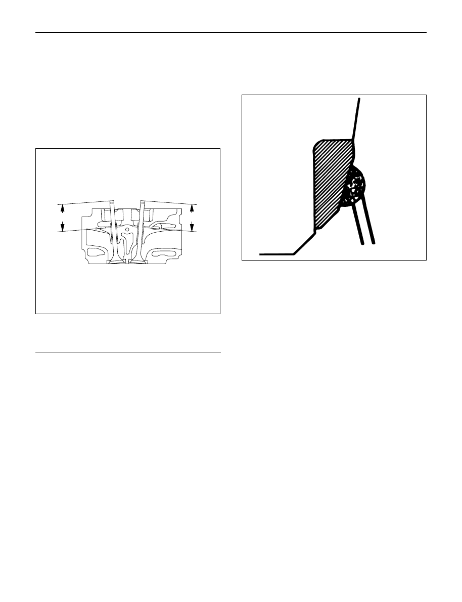
Valve Depression

1. Measure the valve stem height from the upper

surface of the cylinder head as shown in the
illustration.

Standard: 
Intake side

35.59 mm (1.4012 in)

Exhaust side 35.49 mm (1.3972 in)

Limit:
Intake side

35.74 mm (1.4071 in)

Exhaust side 35.64 mm (1.4031 in)

Legend

(1) Intake Side
(2) Exhaust Side

Valve Contact Width

1. Check the valve contact faces for roughness and

unevenness. Make the valve contact surfaces
smooth.

2. Measure the valve contact width.

If the measured value exceeds the specified limit,
the valve seat insert must be replaced.

Inlet
Standard: 2.1 mm (0.0827 in)
Limit: 2.6 mm (0.1024 in)

Exhaust
Standard: 2.0 mm (0.0787 in)
Limit: 2.5 mm (0.0984 in)

Valve Seat Insert Replacement

Valve Seat Insert Removal

1. Arc weld the entire inside circumference of the

valve seat insert.

2. Allow the valve seat insert to cool for a few minutes.

This will invite contraction and make removal of the
valve seat insert easier.

3. Use a screwdriver to pry the valve seat insert free.

Take care not to damage the cylinder head.

4. Carefully remove carbon and other foreign material

from the cylinder head insert bore.

1

2

011RW044

014RS015

ENGINE MECHANICAL 6A – 65

Valve Seat Insert Installation

1. Carefully place the attachment (1) (having a smaller

outside diameter than the valve seat insert) on the
valve seat insert (2).

Legend

(1) Attachment
(2) Valve Seat Insert
(3) Bench Press

NOTE: The smooth side of the attachment must contact
the valve seat insert.

2. Use a bench press (3) to gradually apply pressure

to the attachment and press the valve seat insert
into place.

Note: Do not apply an excessive amount of pressure
with the bench press. Damage to the valve seat insert
will result.

Valve Seat Insert Correction

1. Remove the carbon from the valve seat insert

surface.

2. Use a valve cutter (15°, 45° and 75° blades) to

minimize scratches and other rough areas. This will
bring the contact width back to the standard value.
Remove only the scratches and rough areas. Do
not cut away too much. Take care not to cut away
unblemished areas of the valve seat surface.

Valve Seat Angle: 45°

NOTE: Use an adjustable valve cutter pilot.
Do not allow the valve cutter pilot to wobble inside the
valve guide.

3. Apply abrasive compound to the valve seat insert

surface.

4. Insert the valve into the valve guide.
5. Turn the valve while tapping it to fit the valve seat

insert.

6. Check that the valve contract width is correct.
7. Check that the valve seat insert surface is in

contact with the entire circumference of the valve.

3

2

1

012RW055

150

°

90

°

30

°

012RW056

014RS014

6A – 66 ENGINE MECHANICAL

INSTALLATION

1. Valve stem seal

1) Use the special tool to install the stem seal to the

valve guide.

Stem Seal Installer: 5-8840-2033-0

2. Valve spring.

1) Install the lower valve seat spring, valve spring,

then the upper valve spring seat.

2) Use valve spring compressor to compress the

spring then install the split collar.

Valve spring compressor: 5-8840-2441-0

NOTE: Make sure the split collar installs completely.

3. Install cylinder head assembly.

Refer to “Cylinder Head” in this manual.

4. Install the camshaft carrier with camshaft.

Refer to “Camshaft” in this manual.

5. Install oil rail assembly.

Refer to “Oil rail and injector” in this manual.

6. Install injector assembly.

Refer to “Oil rail and injector” in this manual.

7. Install the injector harness assembly.

Refer to “Injector” in this manual.

8. Reconnect harness connecter to oil pressure

sensor and oil temperature sensor on the oil rail.

9. Reconnect Injector harness connecter to injector.

Refer to “Injector” in this manual.

10. Install cylinder head cover with gasket.

Refer to “Cylinder Head Cover” in this manual.

11. Install glow plug with specified torque.

Torque: 15 N·m (1.5 kg·m / 11 lb ft)

12. Install the intake manifold assembly.

Refer to “Intake Manifold” in this manual.

13. Install the fuel pipe.

14. Install the water pipe between the cylinder head

and water pump.

Torque: 20 N·m (2.0 k·m / 14 lb ft)

15. Install the front plate.
16. Install the camshaft pulley.

Refer to “Timing Gear” in this manual.

17. Install timing belt and set the tensioner.

Refer to “Timing Belt” in this manual.

18. Install CMP sensor bracket.

Torque: 20 N·m (2.0 kg·m / 14 lb ft)

19. Install timing belt cover.

Torque: 9 N·m (0.9 kg·m / 78 lb in)

20. Fill the oil rail with engine oil then immediately

install the high pressure oil pipe with the specified
torque.

Torque: 78 N·m (8.0 kg·m / 58 lb ft)

21. Install the noise insulator cover.
22. Reconnect hose between thermostat and radiator.
23. Install turbocharger assembly.

Refer to “Turbocharger” in this manual.

24. Install water hose and oil pipe for turbocharger.

Refer to “Turbocharger” in this manual.

25. Install the valve assembly and install heat protector.
26. Install generator and set the fan belts.
27. Install A/C compressor bracket, compressor

assembly and set drive belt.

28. Reconnect harness connector around cylinder

head.

29. Reconnect vacuum hose to EGR valve.
30. Reconnect PCV hose.
31. Install oil level gauge guide assembly.
32. Install intercooler assembly.

Refer to “Intercooler” in this manual.

33. Install the air duct assembly.
34. Fill engine coolant.
35. Connect battery ground cable.

014RW042

ENGINE MECHANICAL 6A – 67

VALVE CLEARANCE ADJUSTMENT

NOTE: 

1. Valve clearance should be inspected and adjusted

while the engine is cool.

2. The tightening of the camshaft bearing cap and

camshaft carrier assembly should be checked
before inspecting and adjusting valve clearance.

INSPECTION

1. Remove cylinder head noise insulator cover and

cylinder head cover.
Refer to “Cylinder Head” in this manual.

2. Disconnect all harness connecters of the injector

and remove harness assembly.

3. Drain oil from oil rail assembly.
4. Remove injector clamp nuts and fixing bolts to take

out injector assembly.

5. Loosen oil rail bolts, remove oil rail assembly.
6. Set cylinder No.1 to the TDC at the compression

stroke. Make sure that there is play in cylinder No.1
tappets on inlet and exhaust sides and that there is
no play in cylinder No.4 tappets.

7. Measure valve clearance at No.1 TDC (Refer to the

black circles indicated in the illustration).

Standard Valve clearance:

Intake valve:

0.15 mm (0.0059 in) ± 0.05 mm (0.0020 in)

Exhaust valve: 0.25 mm (0.0098 in) ± 0.05 mm (0.0020 in)

8. Turn the crankshaft one turn to set No.4 cylinder

TDC at the compression stroke.

9. Measure valve clearance at No.4 TDC (Refer to the

black circles indicated in the illustration).

Standard Valve clearance:

Intake valve:

0.15 mm (0.0059 in) ± 0.05 mm (0.0020 in)

Exhaust valve: 0.25 mm (0.0098 in) ± 0.05 mm (0.0020 in)

10. If measured value is outside standard value,

readjust the valve clearance.

ADJUSTMENT

For valve clearance adjustment, follow the procedure
given below.

1. Set cylinder No.1 or No.4 to the TDC at the

compression stroke.
Set the valve clearance adjusting tool on the tappet
requiring adjustment.
After making sure of the correct setting of the
special tool, depress the tappet by turning the bolt.
Valve Clearance Adjusting Tool: 5-8840-2590-0

NOTE: Before depressing the tappet, set the tappet
notch in the direction where adjuster can be easily
taken out.

2. Take out the adjuster using a small screw driver and

finger magnet.

No.1

Ft

No.2

No.1 TDC

No.3

No.4

EXH

IN

011RW045

No.1

Ft

No.2

No.4 TDC

No.3

No.4

EXH

IN

011RW046

014RW150


Content   ..  562  563  564  565   ..