Infiniti Q45. Manual - part 890


  Index      Infiniti     Infiniti Q45 - service repair manual 2006 year


Search            copyright infringement  


Content   ..  888  889  890  891   ..


Infiniti Q45. Manual - part 890


TROUBLE DIAGNOSIS FOR SYSTEM

STC-63

[WITH REAR ACTIVE STEER]

C

D

E

F

H

I

J

K

L

M

A

B

STC

2. 

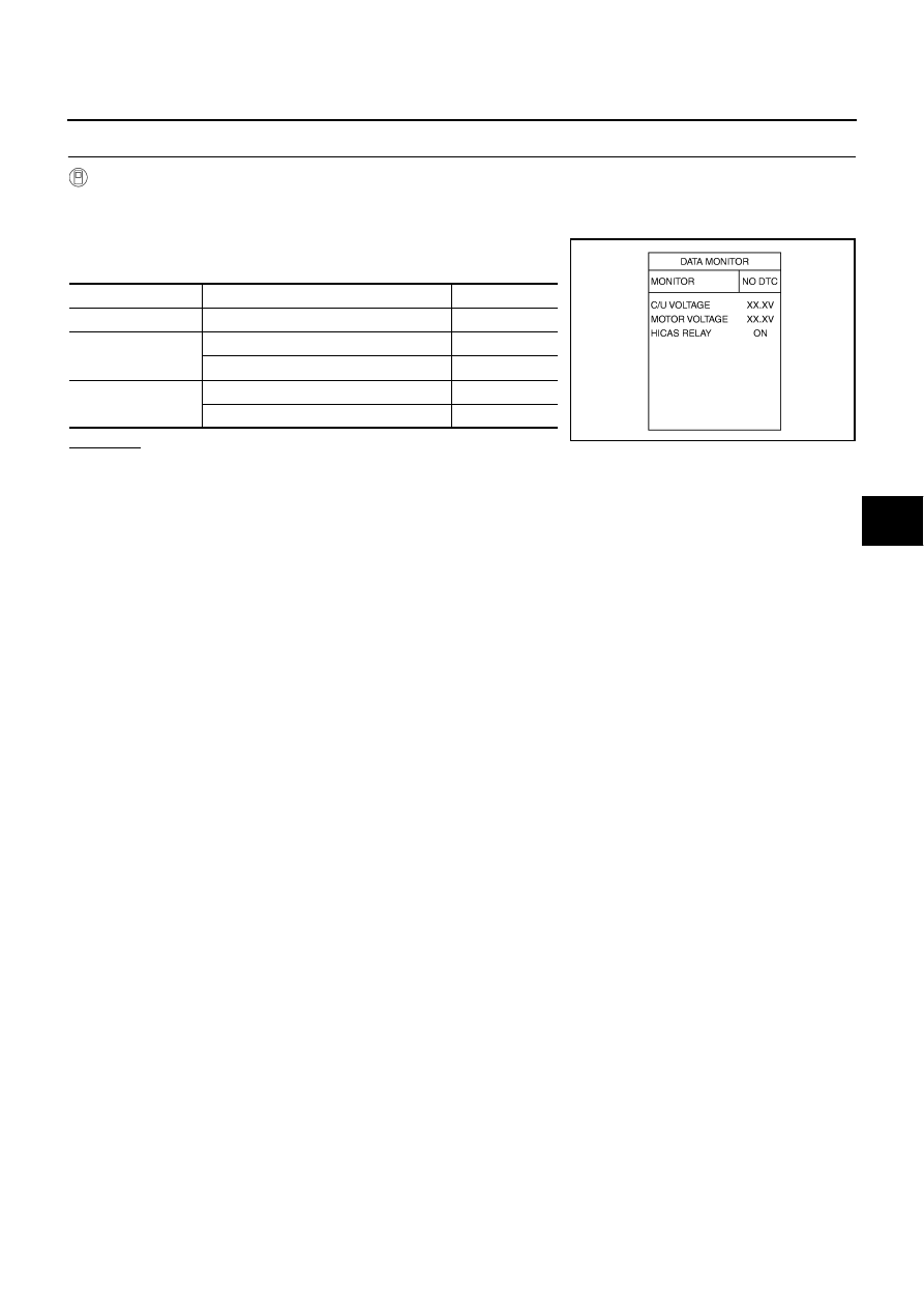
CHECK POWER SUPPLY SIGNAL

 With CONSULT-II

1.

Start engine.

2.

Select “DATA MONITOR” mode for “RAS/HICAS” with CONSULT-II.

3.

Read out the value of “C/U VOLTAGE”, “MOTOR VOLTAGE”
and “HICAS RELAY”.

OK or NG

OK >> GO 

TO 

7.

NG

>> GO TO 3.

Monitored item

Condition

Display value

C/U VOLTAGE

Ignition switch: ON

Battery voltage

MOTOR VOLTAGE

Ignition switch: ON

Battery voltage

Ignition switch: OFF

0 V

HICAS RELAY

Ignition switch: ON

ON

Ignition switch: OFF

OFF

SGIA1477E

STC-64

[WITH REAR ACTIVE STEER]

TROUBLE DIAGNOSIS FOR SYSTEM

3. 

CHECK POWER SUPPLY

1.

Turn ignition switch “OFF”.

2.

Disconnect RAS control unit harness connector.

3.

Check voltage between RAS control unit harness connector (A)
terminals and ground.

4.

Turn ignition switch “ON”. (Do not start engine.)

5.

Check voltage between RAS control unit harness connector (A)
terminals and ground.

OK or NG

OK

>> GO TO 4.

NG

>> Check the following. If any items are damaged, repair or 

replace damaged parts.

10 A fuse [No. 7 located in the fuse block (J/B) No.1]. Refer to 

PG-2, "POWER SUPPLY ROUT-

ING"

 .

20 A fuse [No. 76 located in the fuse, fusible link and relay box]. Refer to 

PG-2, "POWER SUP-

PLY ROUTING"

 .

Harness for short or open between ignition switch and RAS control unit harness connector B39
terminals 27.

Harness for short or open between battery and RAS control unit harness connector B39 termi-
nals 37.

Harness for short or open between RAS control unit harness connector B39 terminal 25 and
RAS motor relay harness connector B42 terminal 1.

Harness for open circuit or short to power between RAS motor relay harness connector B42
terminal 2 and ground.

Battery. Refer to 

PG-2, "POWER SUPPLY ROUTING"

 .

Connector

Terminal

Voltage (Approx.)

B39

25 - Ground

0 V

27 - Ground

37 - Ground

SGIA1464E

Connector

Terminal

Voltage (Approx.)

B39

25 - Ground

Battery voltage

27 - Ground

37 - Ground

SGIA1465E

TROUBLE DIAGNOSIS FOR SYSTEM

STC-65

[WITH REAR ACTIVE STEER]

C

D

E

F

H

I

J

K

L

M

A

B

STC

4. 

CHECK GROUND CIRCUIT

1.

Turn ignition switch “OFF”.

2.

Disconnect RAS control unit harness connector.

3.

Check continuity between RAS control unit harness connector
(A) B39 terminal 40 and ground.

Also check harness for short to power.

OK or NG

OK

>> GO TO 5.

NG

>> Check the following. If any items are damaged, repair or 

replace damaged parts.

Harness open circuit or short to power between noise
suppressor harness connector B41 terminal 4 and
RAS control unit harness connector B39 terminal 40.

Harness open circuit or short to power between noise suppressor harness connector B40 termi-
nal 2 and ground.

5. 

CHECK RAS MOTOR RELAY

1.

Turn ignition switch “OFF”.

2.

Remove RAS motor relay. Refer to 

STC-41, "Component Parts Location"

 .

3.

Apply 12 V direct current between RAS motor relay connector
B42 terminals 1 and 2.

4.

Check continuity between RAS motor relay connector B42 ter-
minals 3 and 5.

5.

Check continuity between RAS motor relay connector B42 ter-
minals 1 and 2.

OK or NG

OK

>> GO TO 6.

NG

>> Replace RAS motor relay.

6. 

CHECK NOISE SUPPRESSOR

1.

Turn ignition switch “OFF”.

2.

Remove noise suppressor. Refer to 

STC-41, "Component Parts Location"

 .

3.

Check noise suppressor connector (A) continuity between the
following terminals.

OK or NG

OK

>> GO TO 7.

NG

>> Replace RAS motor relay.

Continuity should exist.

SGIA1466E

Terminal

Condition

Continuity

3 - 5

1 2 V direct current supply between terminals 1 and 2

Yes

OFF

No

1 – 2

: 74 

SGIA1286E

1 – 3

: Continuity should exist.

1 – 2

: Continuity should no exist.

1 – 4

: Continuity should no exist.

2 – 1

: Continuity should no exist.

2 – 3

: Continuity should no exist.

2 – 4

: Continuity should exist.

SGIA1467E

STC-66

[WITH REAR ACTIVE STEER]

TROUBLE DIAGNOSIS FOR SYSTEM

7. 

CHECK RAS CONTROL UNIT

Check RAS control unit input/output signal. Refer to 

STC-47, "RAS Control Unit Input/Output Signal Refer-

ence Values"

 .

OK or NG

OK

>> GO TO 8.

NG

>> Check RAS control unit pin terminals for damage or loose connection with harness connector. If

any items are damaged, repair or replace damaged parts.

8. 

CHECK DTC

Perform the self-diagnosis, after driving a vehicle for a while.

OK or NG

OK

>> INSPECTION END

NG

>> Replace RAS control unit. Refer to 

STC-90, "Removal and Installation"

 .


Content   ..  888  889  890  891   ..