Infiniti Q45. Manual - part 888


  Index      Infiniti     Infiniti Q45 - service repair manual 2006 year


Search            copyright infringement  


Content   ..  886  887  888  889   ..


Infiniti Q45. Manual - part 888


TROUBLE DIAGNOSIS

STC-55

[WITH REAR ACTIVE STEER]

C

D

E

F

H

I

J

K

L

M

A

B

STC

Inspections before Trouble Diagnosis

NGS0006N

Inspect for power steering fluid leakage and check the power steering fluid level. Refer to 

PS-6, "POWER

STEERING FLUID"

 .

Power steering components (gears, oil pump, pipes, etc.) are free from leakage, and that oil level is cor-
rect.

Tires are inflated to specified pressure and are of specified size, and that steering wheel is a genuine Nis-
san part.

Suspension utilizes the original design, and is free of modifications which increase vehicle weight.

Wheel alignment is adjusted properly.

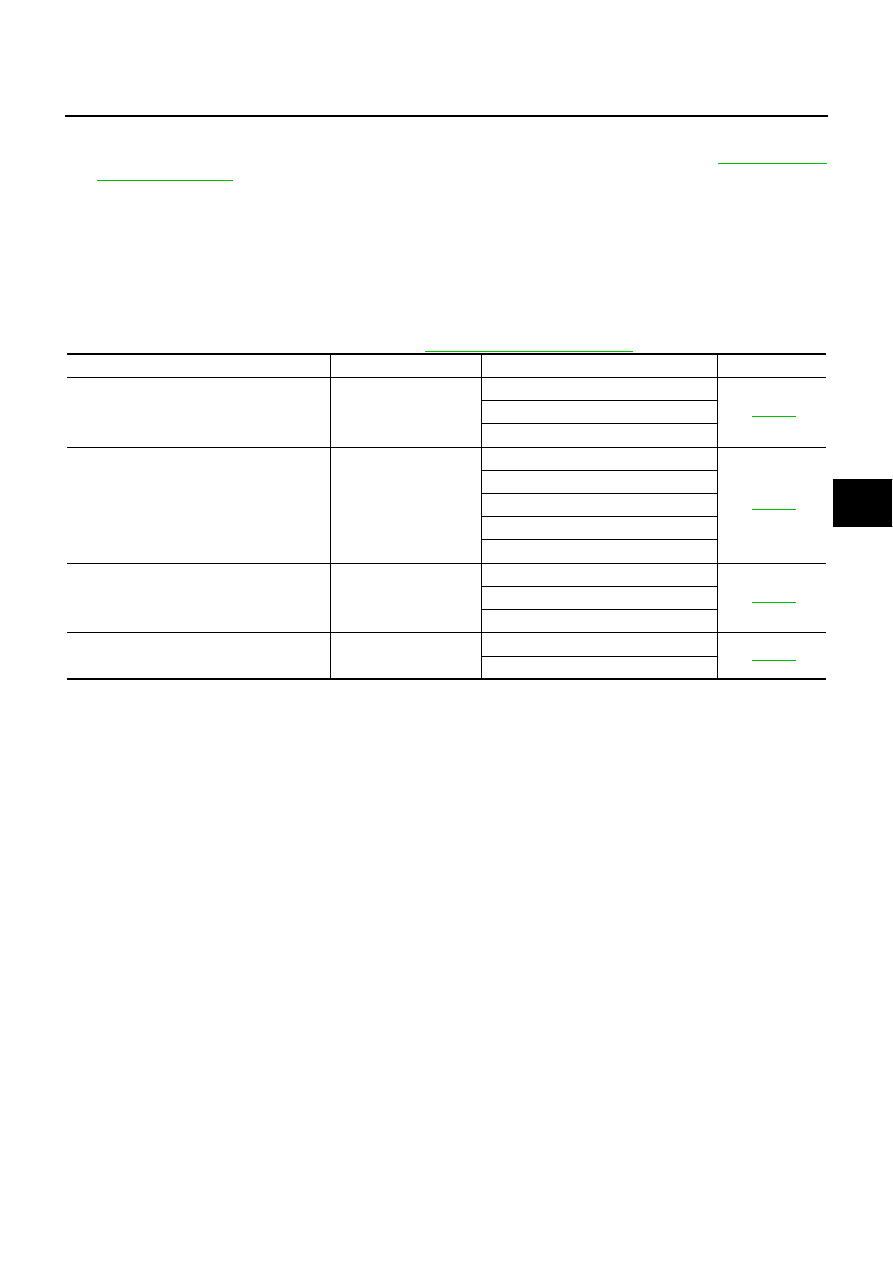
Trouble Diagnosis Chart for Symptoms

NGS0006Q

If RAS warning lamp turns ON, perform self-diagnosis. Refer to 

STC-53, "Self-Diagnostic Procedure"

 .

Symptom

Condition

Check item

Reference page

RAS warning lamp does not turn ON for 
approx.1 second when the ignition switch is 
turned to ON.

Ignition switch: ON

Power supply

STC-85

Combination meter

RAS control unit

The steering force of steering wheel is not 
changed smoothly according to the vehicle 
speed.

While driving

Vehicle speed sensor

STC-87

Stop lamp switch

Power steering solenoid valve

RAS actuator assembly

RAS control unit

Hard steering when fully turning the steering 
wheel.

Vehicle stopped or while 
low speed driving

Vehicle speed sensor

STC-88

Stop lamp switch

Power steering solenoid valve

Light steering when driving at a high speed.

While high speed driving

Vehicle speed sensor

STC-89

Power steering solenoid valve

STC-56

[WITH REAR ACTIVE STEER]

TROUBLE DIAGNOSIS FOR SYSTEM

TROUBLE DIAGNOSIS FOR SYSTEM

PFP:00000

DTC C1900, C1901, C1905, C1906, C1907, C1908, C1922, C1927, C1928 CON-
TROL UNIT

NGS0008H

Check the following if “CONTROL UNIT [ABNORMAL1] [C1900]”, “CONTROL UNIT [ABNORMAL2]
[C1901]”, “CONTROL UNIT [ABNORMAL3] [C1905]”, “CONTROL UNIT [ABNORMAL5] [C1906]”, “CON-
TROL UNIT [ABNORMAL4] [C1907]”, “CONTROL UNIT [ABNORMAL7] [C1908]”, “CONTROL UNIT
[ABNORMAL8] [C1922]”, “CONTROL UNIT [ABNORMAL5] [C1927]” or “CONTROL UNIT [ABNORMAL9]
[C1928]” is detected in self-diagnosis results with CONSULT-II or “flickering pattern for 11” is detected in
self-diagnosis results without CONSULT-II.

DIAGNOSTIC PROCEDURE

1. 

INSPECTION START

Is CONSULT-II available?

YES or NO

YES

>> GO TO 2.

NO

>> GO TO 3.

2. 

PERFORM SELF-DIAGNOSIS (WITH CONSULT-II)

 With CONSULT-II

1.

Turn ignition switch “ON”. (Do not start engine.)

2.

Select “SELF-DIAG RESULTS” mode for “RAS/HICAS” with CONSULT-II.

3.

Touch “ERASE”.

4.

Turn ignition switch “OFF” and wait at least 10 seconds.

5.

Perform the self-diagnosis again.

Is the “CONTROL UNIT [ABNORMAL1] [C1900]”,  “CONTROL UNIT [ABNORMAL2] [C1901]”,  “CONTROL
UNIT [ABNORMAL3] [C1905]”, “CONTROL UNIT [ABNORMAL5] [C1906]”, “CONTROL UNIT [ABNORMAL4]
[C1907]”, “CONTROL UNIT [ABNORMAL7] [C1908]”, “CONTROL UNIT [ABNORMAL8] [C1922]”, “AD CON-
VERTER [C1925]”, “CONTROL UNIT [ABNORMAL5] [C1927]” or “CONTROL UNIT [ABNORMAL9] [C1928]”
displayed?

YES

>> Replace RAS control unit. Refer to 

STC-90, "Removal and Installation"

 .

NO

>> INSPECTION END

3. 

PERFORM SELF-DIAGNOSIS (WITHOUT CONSULT-II)

 Without CONSULT-II

1.

Perform the self-diagnosis and then erase self-diagnostic results. Refer to 

STC-53, "SELF-DIAGNOSTIC

PROCEDURE (WITHOUT CONSULT-II)"

  an

STC-54, "ERASE SELF-DIAGNOSIS"

 .

2.

Perform the self-diagnosis again.

Do the self-diagnostic results indicate RAS control unit?

YES

>> Replace RAS control unit. Refer to 

STC-90, "Removal and Installation"

 .

NO

>> INSPECTION END

DTC C1925 AD CONVERTER

NGS000CS

Check the following if “AD CONVERTER [C1925]” is detected in self-diagnosis results with CONSULT-II
or “flickering pattern for 11” is detected in self-diagnosis results without CONSULT-II.

Refer to 

STC-56, "DTC C1900, C1901, C1905, C1906, C1907, C1908, C1922, C1927, C1928 CONTROL

UNIT"

 .

TROUBLE DIAGNOSIS FOR SYSTEM

STC-57

[WITH REAR ACTIVE STEER]

C

D

E

F

H

I

J

K

L

M

A

B

STC

DTC C1902, C1903, C1904, C1910, C1913 MOTOR OUTPUT

NGS0008I

Check the following if “MOTOR OUTPUT [REV CURRENT] [C1902]”, “MOTOR OUTPUT [NO CURRENT]
[C1903]”, “MOTOR OUTPUT [OVERCURRENT] [C1904]”, “MOTOR OUTPUT [MOTOR LOCK] [C1910]”
or “MOTOR OUTPUT [ABNORML SIG] [C1913]” is detected in self-diagnosis results with CONSULT-II or
“flickering pattern for 13” is detected in self-diagnosis results without CONSULT-II.

CONSULT-II REFERENCE VALUE IN DATA MONITOR MODE

Data are reference value.

RAS CONTROL UNIT TERMINALS AND REFERENCE VALUE

Data are reference value and are measured between each terminal and ground.

CAUTION:

When using a circuit tester to measure voltage for inspection, be sure not to extend forcibly any connector terminals.

Monitored item

Content

Condition

Display value

MOTOR VOLTAGE [V]

Monitored value of voltage at 
RAS motor

Ignition switch: ON

Battery voltage

Ignition switch: OFF

0 V

MOTOR CURRENT [A]

Monitored value of current at 
RAS motor

During RAS actuator assembly turning

Approx. 0 - 20 A

MTR CRNT OPE [A]

Current commanded value to 
RAS motor

During RAS actuator assembly turning

Approx. -20 - 20 A

Terminal

Wire 

color

Item

Condition

Data (Approx.)

38

G/Y

RAS motor output voltage
(right)

While RAS motor is operating for right

Battery voltage

While RAS motor is operating for left

0 V

39

G/R

RAS motor output voltage
(left)

While RAS motor is operating for right

0 V

While RAS motor is operating for left

Battery voltage

STC-58

[WITH REAR ACTIVE STEER]

TROUBLE DIAGNOSIS FOR SYSTEM

DIAGNOSTIC PROCEDURE

1. 

CHECK RAS MOTOR SIGNAL

 With CONSULT-II

1.

Start engine.

2.

Select “DATA MONITOR” mode for “RAS/HICAS” with CONSULT-II.

3.

Read out the value of “MOTOR VOLTAGE”, “MOTOR CUR-
RENT” and “MTR CRNT OPE”.

 Without CONSULT-II

1.

Start engine.

2.

Check voltage between RAS control unit harness connector (A)
terminals and ground.

OK or NG

OK >> GO 

TO 

4.

NG

>> GO TO 2.

2. 

CHECK HARNESS BETWEEN RAS CONTROL UNIT AND RAS MOTOR

1.

Turn ignition switch “OFF”.

2.

Disconnect RAS control unit harness connector and RAS motor harness connector.

3.

Check continuity between the following terminals.

RAS control unit harness connector (A) B39 terminal 38 and
RAS motor harness connector (B) B82 terminal 1.

RAS control unit harness connector (A) B39 terminal 39 and
RAS motor harness connector (B) B82 terminal 2.

Also check harness for short to ground and short to power.

OK or NG

OK

>> GO TO 3.

NG

>> Repair or replace damaged parts.

Monitored item

Condition

Display value

MOTOR VOLTAGE

Ignition switch: ON

Battery voltage

Ignition switch: OFF

0 V

MOTOR CURRENT

During RAS actuator assembly turning

Approx. 0 - 20 A

MTR CRNT OPE

During RAS actuator assembly turning

Approx. -20 - 20 A

Connector

Terminal

Condition

Voltage 

(Approx.)

B39

38 - 

Ground

While RAS motor is operating for right

Battery 
voltage

While RAS motor is operating for left

0 V

39 - 

Ground

While RAS motor is operating for right

0 V

While RAS motor is operating for left

Battery 
voltage

SGIA1469E

SGIA1470E

Continuity should exist.

SGIA1472E


Content   ..  886  887  888  889   ..