Infiniti Q45. Manual - part 889
TROUBLE DIAGNOSIS FOR SYSTEM
STC-59
[WITH REAR ACTIVE STEER]
C
D
E
F
H
I
J
K
L
M
A
B
STC
3.
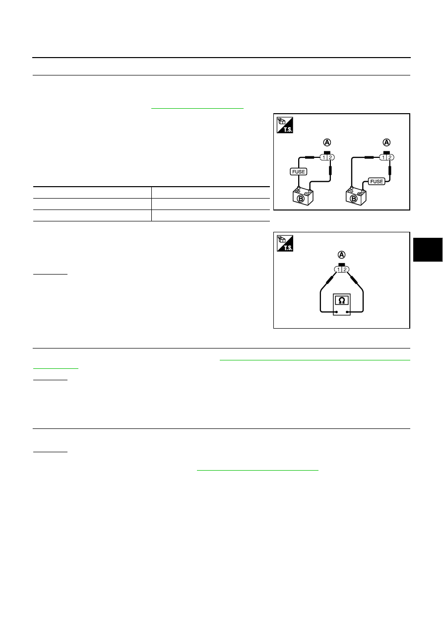
CHECK RAS MOTOR
1.
Turn ignition switch “OFF”.
2.
Disconnect RAS motor harness connector.
3.
Remove RAS motor. Refer to
4.
Check operation by supply 6 V (B) voltage to RAS motor con-
nector (A) terminals 1 and 2.
CAUTION:
●
Never supply 12 V voltage (battery, etc.) to the RAS
motor.
●
Never operate RAS motor for more than 1 second.
●
Be careful not to overheat the harness.
5.
Check continuity between RAS motor connector (A) terminals 1
and 2.
OK or NG
OK
>> GO TO 4.
NG
>> Replace RAS motor.
4.
CHECK RAS CONTROL UNIT
Check RAS control unit input/output signal. Refer to
STC-47, "RAS Control Unit Input/Output Signal Refer-
.
OK or NG
OK
>> GO TO 5.
NG
>> Check RAS control unit pin terminals for damage or loose connection with harness connector. If
any items are damaged, repair or replace damaged parts.
5.
CHECK DTC
Perform the self-diagnosis, after driving a vehicle for a while.
OK or NG
OK
>> INSPECTION END
NG
>> Replace RAS control unit. Refer to
STC-90, "Removal and Installation"
.
Terminal
Actuator motor
1 (Positive) - 2 (Negative)
Clockwise rotate
2 (Positive) - 1 (Negative)
Counterclockwise rotate
SGIA1473E
1 – 2
: Approx. 0.45
Ω
SGIA1474E