Infiniti Q45. Manual - part 115


  Index      Infiniti     Infiniti Q45 - service repair manual 2006 year


Search            copyright infringement  


Content   ..  113  114  115  116   ..


Infiniti Q45. Manual - part 115


TROUBLE DIAGNOSIS

ATC-55

C

D

E

F

G

H

I

K

L

M

A

B

ATC

5. 

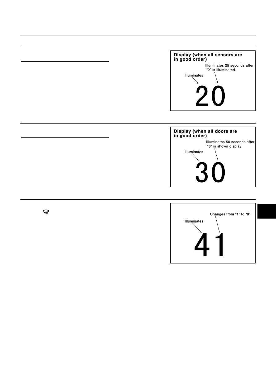
STEP-2: SENSOR CIRCUITS ARE CHECKED FOR OPEN OR SHORT CIRCUIT

Turn temperature dial (driver side) clockwise.

Does code No.20 appear on the display?

YES

>> GO TO 6.

NO

>> GO TO 14.

6. 

STEP-3: MODE DOOR AND INTAKE DOOR POSITIONS ARE CHECKED

Turn temperature dial (driver side) clockwise.

Does code No.30 appear on the display?

YES

>> GO TO 7.

NO

>> GO TO 15.

7. 

STEP-4: OPERATION OF EACH ACTUATOR IS CHECKED

1.

Turn temperature dial (driver side) clockwise.

2.

Press

(DEF) switch, code No. of each actuator test is indi-

cated on the display.

>> GO TO 8.

RJIA0219E

RJIA0220E

RJIA0221E

ATC-56

TROUBLE DIAGNOSIS

8. 

CHECK ACTUATORS

Refer to the following chart and confirm discharge air flow, air temperature, blower motor duty ratio and com-
pressor operation.

Checks must be made visually, by listening to any noise, or by touching air outlets with hand, etc. for improper
operation.

OK or NG

OK

>> GO TO 9.

NG

>>

Air outlet does not change.
Go to Mode Door Motor Circuit. Refer to 

ATC-70, "Mode Door Motor Circuit"

 .

Intake door does not change.
Go to Intake Door Motor Circuit. Refer to 

ATC-76, "Intake Door Motor Circuit"

 .

Discharge air temperature does not change.
Go to Air Mix Door Motor Circuit. Refer to 

ATC-73, "Air Mix Door Motor Circuit"

 .

Blower motor operation is malfunctioning.
Go to Blower Motor Circuit. Refer to 

ATC-81, "Blower Motor Circuit"

 .

Magnet clutch does not engage.
Go to Magnet Clutch Circuit. Refer to 

ATC-86, "Magnet Clutch Circuit"

 .

Code No.

41

42

43

44

45

46

47

48

Mode door position
(Driver side)

VENT

(B/L 

OPEN)

VENT

(B/L 

SHUT)

B/L 1

(B/L 

SHUT)

B/L 1

(B/L 

OPEN)

B/L 2

FOOT

D/F

DEF

Mode door position
(Passenger side)

VENT

(B/L 

OPEN)

VENT

(B/L 

SHUT)

B/L 1

(B/L 

SHUT)

B/L1

(B/L 

OPEN)

B/L 2

FOOT 1

FOOT 2

DEF

Intake door position

REC

REC

REC

20% FRE

20% FRE

FRE

FRE

FRE

Air mix door position

FULL 

COLD

FULL 

COLD

FULL 

COLD

FULL HOT

FULL HOT

FULL HOT

FULL HOT

FULL HOT

Blower motor duty ratio

37%

37%

91%

65%

65%

65%

65%

91%

Compressor

ON

ON

ON

OFF

OFF

OFF

ON

ON

Rear vent door position

OPEN

SHUT

SHUT

SHUT

SHUT

SHUT

SHUT

SHUT

Electronic control valve 
(ECV) duty ratio

100%

50%

100%

0%

0%

0%

50%

100%

RJIA0222E

TROUBLE DIAGNOSIS

ATC-57

C

D

E

F

G

H

I

K

L

M

A

B

ATC

9. 

STEP-5: TEMPERATURE OF EACH SENSOR IS CHECKED

1.

Turn the temperature dial (driver side) clockwise.

2.

Code No. 51 appears on the display.

>> GO TO 10.

10. 

CHECK AMBIENT SENSOR

Press

(DEF) switch one time. Temperature detected by ambient

sensor is indicated on the display.

NOTE:
If temperature shown on display greatly differs from actual tempera-
ture, check sensor circuit first, then inspect sensor.

OK or NG

OK

>> GO TO 11.

NG

>> Go to Ambient Sensor Circuit. Refer to 

ATC-110, "Ambi-

ent Sensor Circuit"

 .

11. 

CHECK IN-VEHICLE SENSOR

Press

(DEF) switch the second time. Temperature detected by in-

vehicle sensor is indicated on the display.

NOTE:
If temperature shown on display greatly differs from actual tempera-
ture, check sensor circuit first, then inspect sensor.

OK or NG

OK

>> GO TO 12.

NG

>> Go to In-vehicle Sensor Circuit. Refer to 

ATC-112, "In-

Vehicle Sensor Circuit"

 .

12. 

CHECK INTAKE SENSOR

Press

(DEF) switch the third time. Temperature detected by intake

sensor is indicated on the display.

NOTE:
If temperature shown on display greatly differs from actual tempera-
ture, check sensor circuit first, then inspect sensor.
OK or NG

OK

>> GO TO 13.

NG

>> Go to Intake Sensor Circuit. Refer to 

ATC-118, "Intake

Sensor Circuit"

 .

RJIA0223E

RJIA1271E

RJIA1272E

ATC-58

TROUBLE DIAGNOSIS

13. 

CHECK MULTIPLEX COMMUNICATION ERROR

1.

Press intake switch.

2.

Multiplex communication error between AV C/U (AV and NAVI
C/U) and auto amp. can be detected as self-diagnosis results.
(If plural errors occur, the display of each error will blink two
times for 0.5 second intervals.)

3.

Is multiplex communication error detected as self-diagnosis
results?

CAUTION:

Rear control cancel switch has two positions “CANCEL” and
“ON”. If rear control cancel switch has been canceled, Multiplex
communication error might be detected even there is no mal-
function.
So it is necessary to follow the procedure below:

1.

Switch “ON” position on the rear control cancel switch.

2.

Disconnect the battery negative terminal for approx. 10 seconds or more in order to delete the
memory of self-diagnosis.

3.

Reconfirm the multiplex communication error as self-diagnosis result is detected.

YES or NO

YES

>> Go to Multiplex Communication Circuit. Refer to 

ATC-120, "Multiplex Communication Circuit"

 .

NO

>> 1. Turn ignition switch OFF or AUTO switch ON.

2. INSPECTION END

RJIA1589E


Content   ..  113  114  115  116   ..