Infiniti Q45. Manual - part 114
TROUBLE DIAGNOSIS
ATC-51
C
D
E
F
G
H
I
K
L
M
A
B
ATC
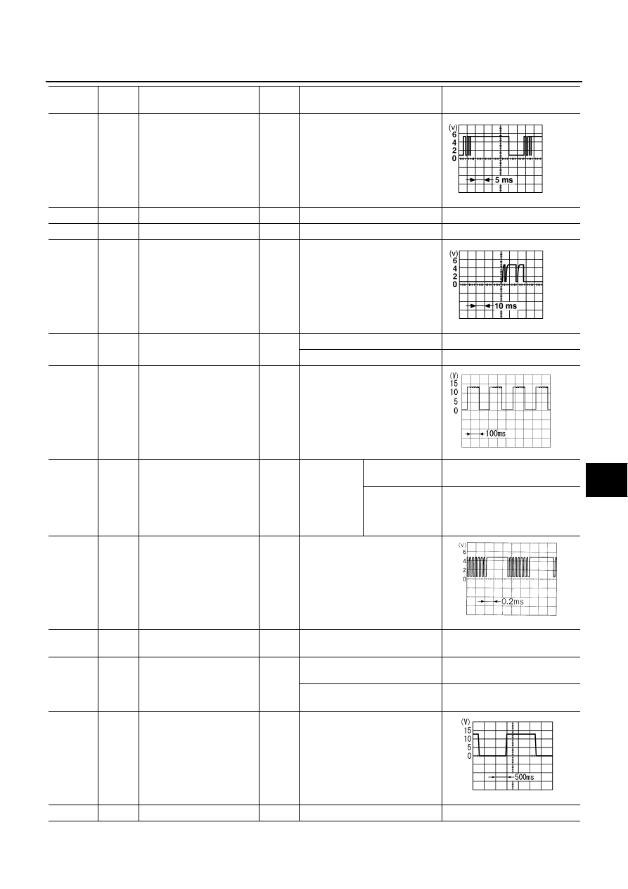
10
R
Multiplex communication
signal (Fr RX)
ON
—
11
R/Y
Sensor ground
ON
—
Approx. 0
12
SB
Sunload sensor
—
—
—
15
G
Multiplex communication
signal (Rr RX)
ON
—
16
W/B
Power supply for rear vent
door motor
ON
Rear vent switch: Open
Approx. 12
Rear vent switch: Close
Approx. 0
17
L/OR
Water temperature sensor
—
At idle [after warming up, approx.
80
°
C (176
°
F)]
NOTE:
The waveforms vary depending
on coolant temperature.
18
OR
Compressor feedback sig-
nal (Low-pressure cut)
ON
AUTO SW:
ON (Start
engine)
Blower motor
operates.
Approx. 0
When refrigerant
pressure sensor
connector is dis-
connected
Approx. 5
20
B
Multiplex communication
signal (Fr CLK)
ON
—
21
GY
Power supply for each door
motor
ON
—
Battery voltage
22
Y/B
Compressor ON signal
ON
AUTO switch: ON
(Blower motor operates.)
Approx. 0
AUTO switch: OFF
(A/C system: OFF)
Approx. 5
23
Y
ECV (Electronic Control
Valve) signal
ON
Self-diagnosis: STEP- 4. (Code
No. 42)
25
B
Ground
ON
—
Approx. 0
Terminal
No.
Wire
color
Item
Ignition
switch
Condition
Voltage
(V)
RJIA0213E
RJIA0214E
PKIA0098J
HAK0363D
RJIA1563E