Infiniti G37 Coupe. Manual - part 418


  Index      Infiniti     Infiniti G37 Coupe - service repair manual 2008 year


Search            


Content   ..  416  417  418  419   ..


Infiniti G37 Coupe. Manual - part 418


DOOR LOCK

DLK-233

< ON-VEHICLE REPAIR >

[INTELLIGENT KEY SYSTEM]

C

D

E

F

G

H

I

J

L

M

A

B

DLK

N

O

P

INSIDE HANDLE : Exploded View

INFOID:0000000001736723

INSIDE HANDLE : Removal and Installation

INFOID:0000000001722622

REMOVAL

1.

Remove the door finisher. Refer to 

INT-11, "Removal and Installation"

.

2.

Remove the inside handle mounting bolts.

3.

Disconnect the inside handle cable, and then remove the inside handle.

INSTALLATION

Install in the reverse order of removal.

CAUTION:

• Check the door lock/unlock operation after installation.
• Check the door open/close operation after installation.
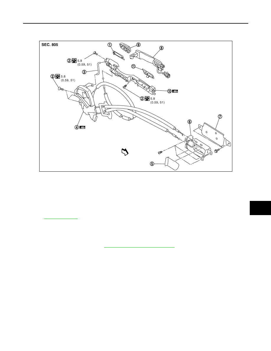
OUTSIDE HANDLE

1.

Rear gasket 

2.

TORX bolt

3.

Key cylinder rod (Driver side only)

4.

Door lock assembly

5.

Inside handle cap

6.

Inside handle

7.

Inside handle bracket

8.

Outside handle

9.

Door key cylinder assembly (Driver 
side)
Outside handle escutcheon (Pas-
senger side)

10. Outside handle bracket

11.

Front gasket

Refer to 

GI-4, "Components"

 for symbols in the figure.

JMKIA1220GB

DLK-234

< ON-VEHICLE REPAIR >

[INTELLIGENT KEY SYSTEM]

DOOR LOCK

OUTSIDE HANDLE : Exploded View

INFOID:0000000001736724

OUTSIDE HANDLE : Removal and Installation

INFOID:0000000001722624

REMOVAL

1.

Remove the door finisher. Refer to 

INT-11, "Removal and Installation"

.

2.

Remove the door glass and door module assembly. 
• Door glass: Refer to 

GW-16, "Removal and Installation"

.

• Door module: Refer to 

GW-19, "Removal and Installation"

.

3.

Remove the door side grommet, and loosen door key cylinder assembly (driver side) and outside handle
escutcheon (passenger side) TORX bolt from grommet hole.

CAUTION:

1.

Rear gasket 

2.

TORX bolt

3.

Key cylinder rod (Driver side only)

4.

Door lock assembly

5.

Inside handle cap

6.

Inside handle

7.

Inside handle bracket

8.

Outside handle

9.

Door key cylinder assembly (Driver 
side)
Outside handle escutcheon (Pas-
senger side)

10. Outside handle bracket

11.

Front gasket

Refer to 

GI-4, "Components"

 for symbols in the figure.

JMKIA1220GB

DOOR LOCK

DLK-235

< ON-VEHICLE REPAIR >

[INTELLIGENT KEY SYSTEM]

C

D

E

F

G

H

I

J

L

M

A

B

DLK

N

O

P

Do not forcibly remove the TORX bolt.

4.

Disconnect the door antenna and door request switch connector and remove the harness clamp.

5.

Reach in to separate the key cylinder rod connection (on the handle). 

6.

While pulling the outside handle, remove the door key cylinder
assembly.

7.

Slide toward rear of vehicle, and pull forward to remove the out-
side handle.

8.

Remove the front gasket and rear gasket.

JMKIA0020ZZ

PIIB5809E

JMKIA0967ZZ

PIIB5811E

DLK-236

< ON-VEHICLE REPAIR >

[INTELLIGENT KEY SYSTEM]

DOOR LOCK

9.

Remove the TORX bolt of the outside handle bracket.

10. While pulling the outside handle bracket, slide toward rear of

vehicle to remove the outside handle bracket.

11. Reach in to separate the outside handle cable connection.

INSTALLATION

Install in the reverse order of removal.

CAUTION:

To install each rod, rotate the rod holder until a click is felt.

JMKIA0022ZZ

PIIB5814E

PIIB5815E


Content   ..  416  417  418  419   ..