Content .. 1394 1395 1396 1397 ..
Infiniti G35 (V35) Sedan. Manual - part 1396
TM-276
< REMOVAL AND INSTALLATION >
[5AT: RE5R05A]
TRANSMISSION ASSEMBLY
6.
Remove heat insulator.
7.
Remove rear propeller shaft. Refer to
8.
Remove suspension member stay. Refer to
.
9.
Remove exhaust mounting bracket. Refer to
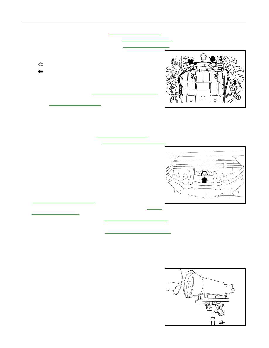
10. Disconnect heated oxygen sensor 2 harness connectors (A).
11. Remove heated oxygen sensor 2 harness (B) from clips (1).
12. Remove bracket (2) from transmission assembly.
13. Remove control rod. Refer to
.
14. Remove crankshaft position sensor (POS) from A/T assembly.
.
CAUTION:
• Do not subject it to impact by dropping or hitting it.
• Do not disassemble.
• Do not allow metal filings, etc. to get on the sensor's front edge magnetic area.
• Do not place in an area affected by magnetism.
15. Remove starter motor. Refer to
.
16. Remove rear plate cover. Refer to
.
17. Turn crankshaft, and remove the four tightening bolts for drive
plate and torque converter.
CAUTION:
When turning the crankshaft, turn it clockwise as viewed
from the front of the engine.
18. Support A/T assembly with a transmission jack.
CAUTION:
When setting the transmission jack, be careful not to allow
it to collide against the drain plug.
19. Remove rear engine mounting member with power tool. Refer to
20. Remove engine mounting insulator (rear). Refer to
21. Remove dynamic damper. Refer to
22. Disconnect A/T assembly harness connector.
23. Remove air breather hose. Refer to
.
24. Remove A/T fluid charging pipe from A/T assembly.
25. Remove O-ring from A/T fluid charging pipe.
26. Disconnect fluid cooler tube from A/T assembly.
27. Plug up openings such as the A/T fluid charging pipe hole, etc.
28. Remove bolts fixing A/T assembly to engine assembly with power tool.
29. Remove A/T assembly from vehicle.
CAUTION:
• Secure torque converter to prevent it from dropping.
• Secure A/T assembly to a transmission jack.
INSTALLATION
: Vehicle front
: Bolt
SCIA8269E
JPDIA0044ZZ
SCIA0499E