Content .. 1392 1393 1394 1395 ..
Infiniti G35 (V35) Sedan. Manual - part 1394
TM-268
< ON-VEHICLE REPAIR >
[5AT: RE5R05A]
AIR BREATHER HOSE
AIR BREATHER HOSE
2WD
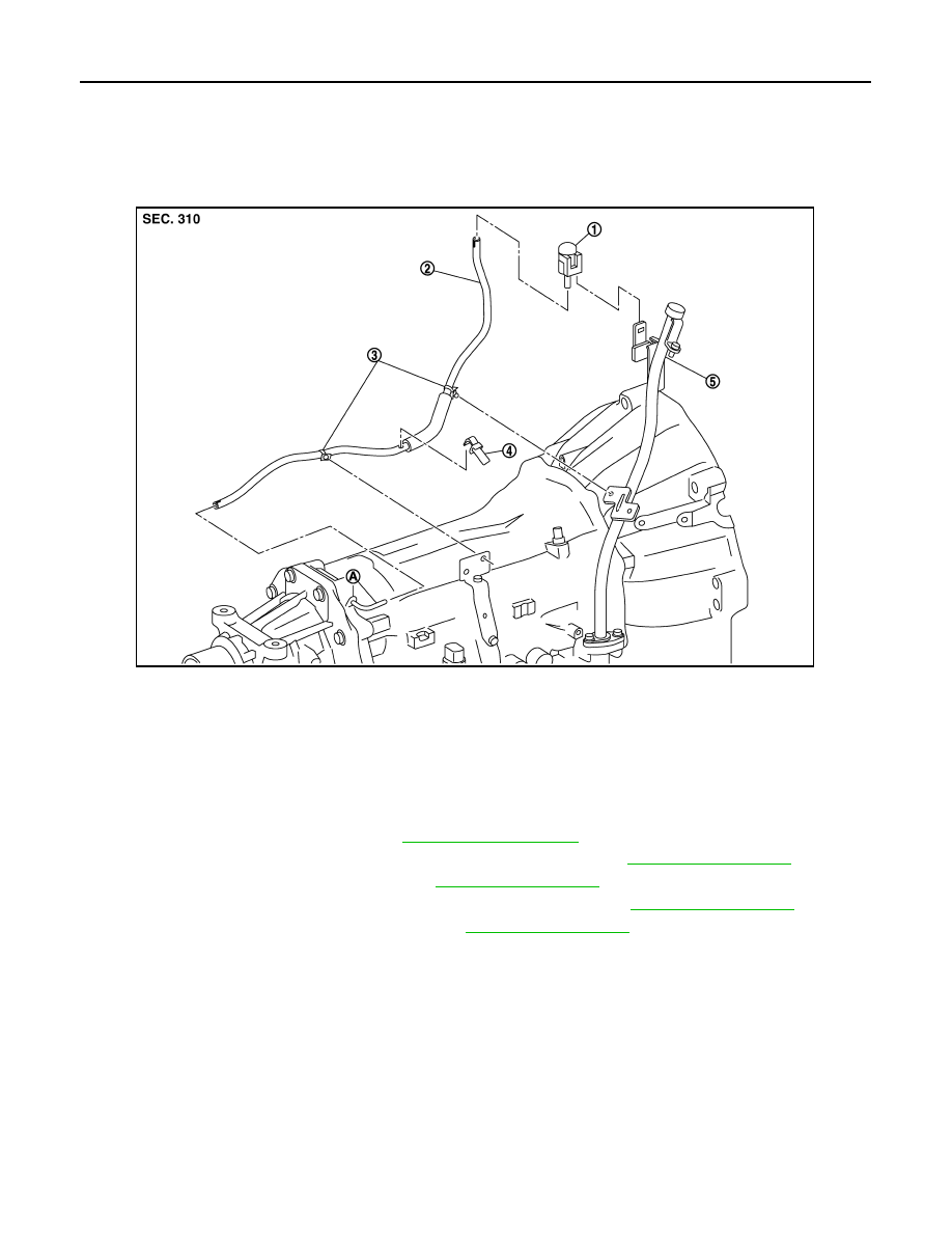
2WD : Exploded View
INFOID:0000000000957170
2WD : Removal and Installation
INFOID:0000000000957171
REMOVAL
1.
Remove air cleaner case (RH). Refer to
2.
Remove exhaust front tube and center muffler with power tool. Refer to
.
3.
Remove exhaust mounting bracket. Refer to
4.
Disconnect heated oxygen sensor (bank 1) harness connector. Refer to
5.
Remove three way catalyst (right bank). Refer to
.
6.
Remove air breather hose.
INSTALLATION
Note the following, and install in the reverse order of removal.
CAUTION:
• When installing an air breather hose, do not to crush or block by folding or bending the hose.
• When inserting an air breather hose to the air breather tube, be sure to insert it fully until its end
reaches the tube bend “R” portion.
• Install A/T air breather hose to air breather tube so that the paint mark is facing upward.
• Ensure clips are securely installed to brackets when installing A/T breather hose to brackets.
• When inserting air breather hose to air breather box, be sure to insert it fully until its end reaches the
stop.
• Install A/T air breather hose to air breather box so that the paint mark is facing backward.
1.
A/T breather box
2.
Air breather hose
3.
Clip
4.
Clip
5.
A/T fluid charging pipe
A.
Air breather tube
JSDIA0135ZZ