Infiniti G35 (V35) Sedan. Manual - part 1389


  Index      Infiniti     Infiniti G35 (V35) Sedan - service repair manual 2007 year


Search            


Content   ..  1387  1388  1389  1390   ..


Infiniti G35 (V35) Sedan. Manual - part 1389


TM-248

< ON-VEHICLE REPAIR >

[5AT: RE5R05A]

CONTROL VALVE WITH TCM

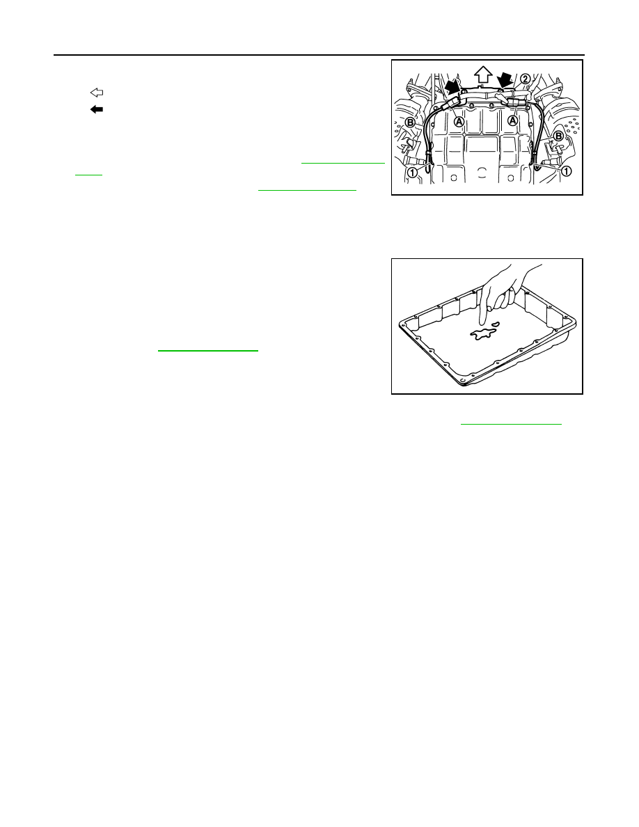
22. Install bracket (2) to transmission assembly.

23. Install heated oxygen sensor 2 harness (B) to clips (1).
24. Connect heated oxygen sensor 2 harness connector (A).

25. Install exhaust mounting bracket. Refer to 

EX-5, "Exploded

View"

.

26. Pour ATF into A/T assembly. Refer to 

TM-218, "Changing"

.

27. Connect the battery cable to the negative terminal.

Inspection

INFOID:0000000000957154

INSPECTION AFTER REMOVAL

Check foreign materials in oil pan to help determine causes of mal-
function. If the ATF is very dark, smells burned, or contains foreign
particles, the frictional material (clutches, band) may need replace-
ment. A tacky film that will not wipe clean indicates varnish build up.
Varnish can cause valves, servo, and clutches to stick and can
inhibit pump pressure.
• If frictional material is detected, perform A/T fluid cooler

cleaning. Refer to 

TM-220, "Cleaning"

.

INSPCTION AFTER INSTALLATION

After completing installation, check for A/T fluid leakage and A/T fluid level. Refer to 

TM-217, "Inspection"

.

: Vehicle front

: Bolt

SCIA8269E

SCIA5199E

A/T FLUID TEMPERATURE SENSOR 2

TM-249

< ON-VEHICLE REPAIR >

[5AT: RE5R05A]

C

E

F

G

H

I

J

K

L

M

A

B

TM

N

O

P

A/T FLUID TEMPERATURE SENSOR 2

Exploded View

INFOID:0000000000957155

Removal and Installation

INFOID:0000000000957156

REMOVAL

1.

Disconnect the battery cable from the negative terminal.

2.

Drain ATF through drain plug.

3.

Remove exhaust mounting bracket. Refer to 

EX-5, "Exploded View"

.

4.

Disconnect heated oxygen sensor 2 harness connectors (A).

5.

Remove heated oxygen sensor 2 harness (B) from clips (1).

6.

Remove bracket (2) from transmission assembly.

1.

A/T

2.

Bracket

3.

Bracket

4.

A/T fluid temperature sensor 2

5.

Clip

6.

Oil pan mounting bolt

7.

Oil pan

8.

Magnet

9.

Drain plug

10. Drain plug gasket

11.

Oil pan gasket

Refer to 

GI-4, "Components"

 for symbols in the figure.

JSDIA0123GB

: Vehicle front

: Bolt

SCIA8269E

TM-250

< ON-VEHICLE REPAIR >

[5AT: RE5R05A]

A/T FLUID TEMPERATURE SENSOR 2

7.

Remove clips (1).

8.

Remove oil pan (2) and oil pan gasket.

9.

Remove magnets (1) from oil pan.

10. Disconnect A/T fluid temperature sensor 2 connector (A).

CAUTION:

Be careful not to damage connector.

11. Disengage terminal clip (

).

12. Remove A/T fluid temperature sensor 2 (1) with bracket (2) from

control valve with TCM.

13. Remove bracket (1) from A/T fluid temperature sensor 2 (2).

3

: Drain plug

: Vehicle front

: Oil pan mounting bolt

SCIA8117E

JPDIA0009ZZ

SCIA8125E

: Bolt

JPDIA0025ZZ

JPDIA0014ZZ

A/T FLUID TEMPERATURE SENSOR 2

TM-251

< ON-VEHICLE REPAIR >

[5AT: RE5R05A]

C

E

F

G

H

I

J

K

L

M

A

B

TM

N

O

P

INSTALLATION

1.

Install bracket (1) to A/T fluid temperature sensor 2 (2).

2.

Install A/T fluid temperature sensor 2 (1) with bracket (2) in con-
trol valve with TCM. Tighten A/T fluid temperature sensor 2 bolts
to the specified torque.

3.

Connect A/T fluid temperature sensor 2 connector (A).

4.

Engage A/T fluid temperature sensor 2 harness with terminal
clip (

).

5.

Install magnets (1) in oil pan.

6.

Install oil pan gasket to oil pan.

CAUTION:

• Do not reuse oil pan gasket.
• Install it in the direction to align hole positions.
• Complete remove all moisture, oil and old gasket, etc.

from oil pan gasket mounting surface.

JPDIA0014ZZ

: Bolt

JPDIA0025ZZ

SCIA8125E

JPDIA0009ZZ


Content   ..  1387  1388  1389  1390   ..